
How to Increase Sensor Inputs Using Multiplexers
You've got a brilliant project idea. Maybe you're building a weather station that needs twelve temperature sensors, or a robotic arm that requires feedback from every joint. You pull out your microcontroller, start counting pins, and realize you're about ten inputs short. Frustrating, right? I've been there more times than I care to admit. The obvious fix is to buy a bigger microcontroller, but that's expensive, wastes board space, and honestly? It's overkill. The smarter move is using multiplexers.
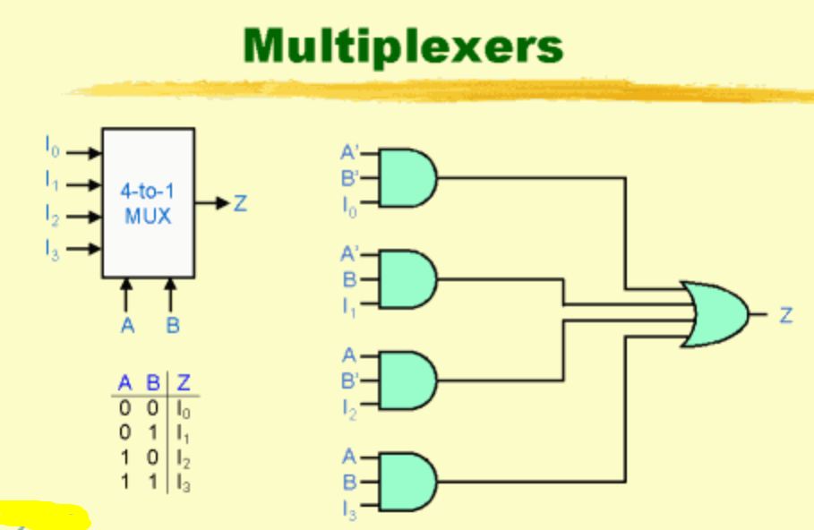
A single multiplexer (or MUX for short) lets you funnel multiple signals into one input. Think of it like a railroad switch. You've got eight trains trying to get onto one track. The MUX decides which train gets through at any given moment. For increasing sensor inputs, this is an absolute game-changer. I've used this trick in everything from industrial PLC replacements to hobbyist greenhouse controllers, and it works every single time.
The beauty here is that you're not actually creating new pins. You're time-sharing. The microcontroller reads one sensor, then the MUX switches to the next one, and so on. It's fast enough that you wont notice the delay. For most sensors—temperature, humidity, pressure, even many analog sensors—the sampling speed is far higher than you need. Let's dive into how you actually make this work.
Why Your Microcontroller Needs a Multiplexer (And You Don't Know It Yet)
The Pin-Shortage Reality Check
I remember my first big project. I was building a multi-zone HVAC controller and needed fourteen thermistors. My Arduino Uno had six analog inputs. I stared at the board for an hour, convinced I'd made a fundamental math error. I hadn't. The solution was a pair of CD4051 multiplexers. Suddenly, two pins gave me sixteen inputs. That's the kind of math that makes engineers smile.
The typical microcontroller has a fixed number of GPIO pins. You've got your power rails, your communication lines (I2C, SPI, UART), maybe a few PWM outputs, and then the analog inputs. For sensor expansion, those analog inputs are gold. But even high-end boards like the ESP32 only give you about eight to sixteen. If you're monitoring a greenhouse, an industrial process, or even a smart home with multiple zones, that runs out fast.
Here's the kicker: many beginners try to solve this with serial communication like I2C. That works for digital sensors, but what about analog sensors? A basic photoresistor or thermistor outputs a varying voltage. You can't just plug that into an I2C bus without an external ADC (analog-to-digital converter). And if you buy an ADC with multiple channels, guess what? It's basically a multiplexer with an ADC built in. You're paying extra for that conversion. If your microcontroller already has an ADC (which most do), you're wasting money.
The Dirty Little Secret About Cost and Board Space
Let's talk real-world constraints. A 16-channel multiplexer chip costs about fifty cents in single quantities. A microcontroller with sixteen analog inputs? You're looking at five to ten dollars, plus a more complex PCB layout, and a steeper learning curve for programming. Seriously, I've seen people redesign entire boards just because they discovered the MUX solution halfway through.
The physical footprint matters too. A single 16-pin SOIC package takes up less space than running a dozen wires to separate ADC chips. For expanding sensor inputs, multiplexers offer the best size-to-channel ratio of any solution. You can cram eight sensors into a space smaller than a postage stamp. The trade-off? Nothing is free. You lose a tiny bit of time because you have to switch channels and settle the signal. But we'll cover how to handle that.
The Technical Playbook: How to Wire Multiplexers for Maximum Sensor Inputs
Picking the Right MUX: Analog vs. Digital
You can't just grab any chip. This is where people mess up. There are two main types: analog multiplexers and digital multiplexers. For sensor signal switching, you want an analog one. Digital multiplexers work with logic levels (0 or 1), but your sensor outputs are continuous voltages. An analog multiplexer passes the voltage exactly as it is, with minimal distortion.
The classic workhorses are the CD4051 (8-channel, single-ended) and the CD4067 (16-channel, single-ended). If you need differential inputs (measuring the difference between two wires), look at the CD4052. I almost always recommend starting with the CD4051. It's cheap, through-hole and SMD packages are available, and it handles voltages from 3V to 15V. For modern 3.3V microcontrollers like the ESP32 or Raspberry Pi Pico, the 74HC4051 is a better choice because it's optimized for lower voltages.
Here's what you need to look for in a datasheet: - On-resistance (Ron): Lower is better. Under 100 ohms is fine for most sensors. Higher resistance can create a voltage divider with your sensor's output impedance, messing up your readings. - Bandwidth: For temperature sensors sampling at 1 Hz, you don't care. For audio sensors or fast photodetectors, you need bandwidth in the megahertz range. - Supply voltage: Match this to your microcontroller and sensor voltage.
Addressing and Timing: The Critical Step Everyone Gets Wrong
The MUX has a set of address pins (A, B, C, sometimes D). These are digital inputs. You connect them to three GPIO pins on your microcontroller. By sending a binary combination (000, 001, 010, etc.), you tell the MUX which channel to connect to the common output pin. It's deceptively simple.
But here's the trap. You write the address, and then immediately read the sensor. That's wrong. The MUX needs time to switch. Think of it like a mechanical relay clicking into place. Even though it's solid-state, there's a propagation delay called the settling time. It's usually in the microsecond range, but for precise analog measurements, you need to wait. I always insert a 10-microsecond delay after setting the address before I read the ADC. This ensures the voltage on the output pin has stabilized. Without this, you'll read garbage from the previous channel. Honestly? This one mistake has cost me more debugging hours than anything else.
Your code should follow this pattern:
1. Set the address pins (digitalWrite on three GPIOs). 2. delayMicroseconds(10). 3. Read the analog input pin. 4. Store the value. 5. Increment the address. 6. Repeat.
If you're using an Arduino, the `analogRead()` function itself has a small delay, but don't rely on that. Be explicit. Look—half the tutorials online skip this step, and then people wonder why their sensor readings are jittery.
Real-World Pitfalls and Pro Tips for Reliable Sensor Data
Signal Integrity and Crosstalk: The Silent Killer
You've got eight sensors connected to a single multiplexer input. You switch between them. Suddenly, channel 2 is showing a reading that looks suspiciously like channel 5. That's crosstalk. It happens because the MUX output pin has parasitic capacitance. When you switch channels, a tiny bit of charge from the previous channel remains.
The fix? Ground unused inputs. If you have a 16-channel MUX but only use 12 sensors, tie the unused channels to ground. This prevents floating voltages from coupling into your measurements. Also, keep your traces short. Long PCB traces act like antennas, picking up noise from the power supply or nearby digital signals. In my experience, running sensors through a multiplexer on a breadboard is fine for prototyping, but for final designs, a proper PCB with a ground plane reduces crosstalk by 90%.
Another pro tip: use a capacitor (0.1 microFarad) between the MUX output and ground. This forms a low-pass filter that smooths out switching transients. But don't go too big. A 10-microFarad cap will cause your readings to lag significantly because the ADC has to charge the cap first. Stick with 0.1 microFarad ceramic.
Power Management and Switching Speed
If you're increasing sensor inputs for a battery-powered project, pay attention to the MUX's power consumption. Most CMOS multiplexers draw negligible current in static mode (microamps). But during switching, they draw a spike. If you're switching at 1 kHz, it doesn't matter. If you're switching at 1 MHz, it starts to add up.
For low-power applications, I use the enable pin on the MUX. Most MUX chips have an Enable pin that disconnects all channels. You can tie this to another GPIO and only enable the MUX when you're about to take a reading. Leave it disabled the rest of the time. This drops power consumption virtually to zero when idle. It's a simple trick that's saved me from adding bigger batteries.
Speed matters too. If you're reading 16 sensors, and each sensor takes 100 microseconds (including MUX settling and ADC conversion), your total scan time is 1.6 milliseconds. That's fast enough for temperature, humidity, and pressure. For audio or vibration analysis, you need faster MUX chips like the 74HC4051, which can handle switching in nanoseconds. But for 90% of sensor applications, the slow and steady approach works perfectly.
Common Questions About How to Increase Sensor Inputs Using Multiplexers
Can I daisy-chain multiple multiplexers for even more sensors?
Yes, and I do this all the time. You can cascade multiplexers by using the output of one MUX as the input to another. For example, two 8-channel MUX chips can give you 64 inputs using only 6 address pins. But the trade-off is increased settling time. Each stage adds more resistance and capacitance. For large arrays (over 32 channels), I usually recommend using an I2C-based MUX or a dedicated ADC with multiple channels. The complexity of address decoding and timing becomes a headache otherwise.
Do multiplexers work with digital sensors like DS18B20?
Not directly. Multiplexers are analog switches. They pass voltages, not protocols. For digital sensors that use OneWire or I2C, you can use a MUX to switch the data line, but you have to be careful. The timing of the communication protocol can get disrupted by the MUX's propagation delay. For I2C sensors, I always use a dedicated I2C MUX (like the TCA9548A) instead of an analog MUX. It handles the protocol correctly. For OneWire sensors, I stick with a digital MUX specifically designed for that protocol, or I just use more GPIO pins.
Will a multiplexer affect the accuracy of my sensor readings?
It can, if you're not careful. The on-resistance of the MUX adds a series resistor to your sensor circuit. If your sensor has an output impedance of 10k ohms and the MUX has 100 ohms on-resistance, the error is about 1%. For most hobbyist projects, that's acceptable. For precision industrial sensors, use a MUX with very low on-resistance (like 5 ohms) and calibrate your system. You can also use a buffer amplifier (like an op-amp voltage follower) between the sensor and the MUX. This presents a high impedance to the sensor and a low impedance to the MUX, virtually eliminating the error.
Can I use a multiplexer with both analog and digital signals?
You can, but I don't recommend it. Mixing analog and digital signals on the same multiplexer invites noise coupling. The fast edges of digital signals can inject noise into the analog channels. If you must do it, use separate MUX chips for analog and digital. Or at least use a MUX with good channel-to-channel isolation (check the datasheet for crosstalk specs). In practice, I keep them separate. It's cleaner and easier to debug.
How do I handle sensors with different voltage outputs?
This is a common issue. You might have a 5V temperature sensor and a 3.3V light sensor. An analog multiplexer doesn't care about the voltage level, as long as it's within the supply rails of the MUX. But your microcontroller's ADC has a maximum input voltage (usually 3.3V or 5V). If you feed a 5V sensor into a 3.3V microcontroller, you'll fry the ADC pin. The fix is a voltage divider on the MUX output, or use a MUX that operates at the higher voltage and then divide the output. I usually just run everything at 3.3V and choose sensors accordingly. It saves headaches.
This approach has worked for me in dozens of projects, from monitoring soil moisture in a hundred-plant garden to reading pressure transducers in a hydraulic test rig. The key is understanding the switching behavior, managing settling time, and keeping your signal paths clean. Multiplexers are one of those tools that seem simple on the surface but have layers of nuance. Master them, and you'll never run out of inputs again.