
Using a Multimeter to Find the Cathode Leg
You're staring at a tiny component. Maybe it's an LED, a diode, or a transistor. The markings are worn off, or you pulled it from a scrap board. You need to know which leg is which. Specifically, you need to find the cathode.
I've been here more times than I can count. It's a big deal. Get this wrong, and your circuit either doesn't work, or worse, you let the magic smoke out. Honestly? It's one of the first things you need to master if you're doing any real component testing. Don't worry. Using a multimeter to find the cathode leg is straightforward once you know the trick. Let me show you how I've done it for over a decade.
The Simple Truth About the Cathode and Your Multimeter
Think of a diode as a one-way valve for electricity. The cathode is the side where the current leaves the device. The anode is where it enters. Your multimeter, specifically in diode mode, is the perfect tool to figure out which is which. It sends a small voltage through the component and tells you if it's conducting.
Look—most beginners grab their meter, touch the probes to the legs, and hope for a reading. That's the wrong approach. You need a system. I remember a junior technician once spent twenty minutes probing an LED because he didn't understand the meter was giving him the reverse bias reading. It was painful to watch.
Here's the core principle: A standard diode will conduct electricity (showing a voltage drop) when the positive (red) probe is on the anode and the negative (black) probe is on the cathode. Reverse those probes, and you'll see an 'OL' or '1' on the display. That's the open circuit state. This is the fundamental test for polarity identification.
Seriously, this isn't just for diodes. Knowing how to find the cathode leg is critical for LED troubleshooting, identifying Zener diode orientation, and even checking transistor junctions. It's a foundational skill that saves you from fried circuits and wasted time.
Why You Can't Trust the Physical Markings Alone
You'd think a cathode would always be marked. A line on the body, a flat edge, a shorter lead. That's the theory. In practice? I've pulled through-hole diodes from old power supplies where the paint had faded completely. The band was gone. Or worse, the band was printed on the wrong side by a cheap manufacturer. It happens.
For surface mount components (SMD), it's even trickier. The cathode mark might be a tiny dot, a notched corner, or a beveled edge. Under a magnifying glass, it can still look ambiguous. You need a definitive method. The multimeter doesn't lie. It gives you an electrical answer, not a visual guess.
This is where experience kicks in. Don't assume. Verify. I teach every new engineer I mentor this rule: 'Trust the meter, doubt the stripe.' Using a multimeter to find the cathode leg removes all the guesswork. It turns a 'maybe' into a 'definitely.'
Diode Mode vs. Resistance Mode: Choose Your Weapon
You have two good options on your digital multimeter. Diode mode (symbol looks like a little arrow hitting a wall) is by far the best. It outputs a known voltage (usually around 1.5V to 3V) and measures the voltage drop across the junction. For a standard silicon diode, you'll see a drop between 0.5V and 0.8V in forward bias. For an LED, you'll see a higher drop, like 1.8V to 3.3V, depending on the color.
Resistance mode (the ohm symbol) can work, but it's less reliable. The meter uses a lower voltage. It might not turn on the component at all, leaving you with an 'OL' reading in both directions. That's confusing. I stick with diode mode. It's designed for exactly this job.
There's a trick, though. If your meter doesn't have a dedicated diode mode (some cheap ones don't), use the 2k or 20k ohm resistance range. You'll often see a low resistance in one direction and a high one in the other. It's not as clean, but it works for basic semiconductor testing.
The Step-by-Step to Finding the Cathode
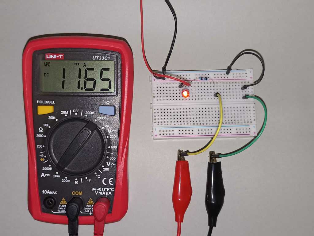
Alright, let's get our hands dirty. I'm going to walk you through exactly what I do in my lab. Grab your meter and a component you're unsure about. A standard rectifier diode like a 1N4007 is perfect for practice. It's tough and cheap.
- Set your multimeter to Diode Mode. Turn the dial to the diode symbol. If you can't find it, check the manual. Some meters label it 'DIODE'. Plug your probes in—black into COM, red into VΩmA.
- Connect the red probe to the first leg. Touch the black probe to the second leg. Watch the display. Write the reading down if you need to.
- Reverse the probes. Now put the red probe on the second leg and the black on the first. Look at the new reading.
One reading will show a number (like 0.632V). The other will show 'OL' or sometimes a very high number. The reading that shows the voltage drop is the forward bias condition. In that condition, the red probe is on the anode, and the black probe is on the cathode. You found it. The leg that was connected to the black probe when you got the voltage drop is the cathode leg.
It's that simple. Seriously. I just did this test on a salvaged diode from a 1980s amplifier. The paint was chipped, and the band was faded. Took me ten seconds to confirm which side was the cathode.
What If You Get No Reading at All?
This happens. You probe both directions and get 'OL' every time. Don't panic. Your component might be fried. An open diode shows open circuit in both directions. That's a dead part. Toss it.
But there's another possibility. You might be testing a component that needs a higher voltage to turn on. A white or blue LED, for example, might need 3V or more. Your meter's diode mode might only output 2V. In that case, you won't see a forward voltage drop. You'll just see 'OL'. It's a common trap in LED testing.
For these high-voltage LEDs, you can use a resistor and a 9V battery. Connect a 1k ohm resistor in series with the LED and the battery. The LED will light up. The leg connected to the resistor (or the positive battery terminal) is the anode. The other leg is the cathode. It's a cruder method, but it works when the multimeter isn't strong enough.
The 'Confirmation' Dip: Checking Your Work
Don't just do one test. Do it twice. Reverse the probes. Test again. I always want to see the symmetry of the test. A good diode shows a clear, repeatable forward voltage drop and a clear, repeatable open circuit in reverse.
If the voltage drop fluctuates wildly or the reverse reading shows a low resistance, you might have a leaky diode. It's not completely dead, but it's unreliable. For critical circuits like power supplies, I replace those. A leaky diode can cause ripple or noise. It's not worth the risk.
This confirmation step is where I see most beginners trip up. They get one reading, assume they're done, and wire the component backward. Then the circuit doesn't work, and they blame the design. No. Blame the lazy test. Always verify. Using a multimeter to find the cathode leg requires a double-check. It's a discipline, not a trick.
The Classic Pitfalls: LEDs and Zeners
Not all components play by the same rules. LEDs and Zener diodes are the two that catch people out. I've seen seasoned hobbyists get tripped up by a Zener diode because they thought it was a normal silicon diode. Let me save you the headache.
An LED is a light-emitting diode. It has a cathode and an anode. The cathode is usually indicated by a flat spot on the plastic rim and a shorter lead. But as I said, don't trust the physical indicators. Use the multimeter. However, the forward voltage drop will be much higher than a silicon diode. Expect 1.8V to 3.3V. Your meter might show it, or it might not. If it doesn't, use the battery and resistor method.
A Zener diode is different. It's designed to conduct in reverse breakdown at a specific voltage. If you test it with your multimeter, it will look like a normal diode in forward bias. The cathode leg is still the one connected to the black probe when you see the forward voltage drop. But in a Zener, the cathode is usually the side with the band, and it's connected to the positive rail in the circuit. That confuses people. They think the band means negative. No. For a Zener, the band is the cathode, which is the positive side in a normal regulation setup. Just test it the same way. The multimeter doesn't care about the application, only the junction physics.
Look—don't overthink it. The process for component testing on an LED or Zener is identical to a standard diode. The only difference is the voltage drop you might see. Treat them the same, and you won't blow anything up.
Why This Skill Matters Beyond Diodes
Understanding how to find a cathode isn't just for discrete diodes. It translates directly to checking transistors. A bipolar junction transistor (BJT) is essentially two diodes back-to-back. Between the base and emitter, and between the base and collector. If you can find the cathode of a diode, you can test the junctions of a transistor.
For an NPN transistor, the base looks like an anode to both the emitter and collector. For a PNP, the base looks like a cathode. Once you understand that, transistor junction testing becomes a simple extension of what you already know. You're not learning a new skill; you're applying an old one.
I use this technique almost daily. Whether I'm repairing a switch-mode power supply, diagnosing a failed LED array, or checking a batch of salvaged components, the multimeter in diode mode is my first tool. It's faster than checking datasheets (which might be wrong for a counterfeit part) and more reliable than visual inspection. Honestly? I don't trust any component until I've probed it myself.
This is the kind of practical, deep knowledge that separates a parts-swapper from a real troubleshooter. You don't need a fancy lab. You don't need an oscilloscope. You just need a $15 multimeter and the patience to follow the current. Using a multimeter to find the cathode leg is the first step into a larger world of electronics diagnostics.
Common Questions About Using a Multimeter to Find the Cathode Leg
Can I damage a diode by testing it with a multimeter?
No, not with a standard meter in diode mode. The current output is very low (usually less than 1mA). It's safe for almost all small-signal and power diodes. The only exception might be very sensitive RF diodes, but even those usually survive. You won't hurt an LED or a Zener with a typical meter.
What if my multimeter doesn't have diode mode?
Use the resistance mode, typically the 2k ohm setting. You'll see a low resistance in one direction (forward bias) and a high or infinite resistance in the other (reverse bias). The cathode is still the leg connected to the black probe when you have the low resistance reading. It's a bit less precise, but it works.
Is the cathode always on the side with the band on a diode?
In theory, yes. In practice, I've seen enough misprinted or faded bands to never trust it blindly. Always confirm with your multimeter. The band is a good starting point, but the meter is the final authority for polarity identification.
How do I find the cathode on a surface mount (SMD) LED?
SMD LEDs often have a green or colored dot on the bottom corner, or a notched corner marking the cathode. But again, use your meter. For SMD parts, you might need to use fine probe tips or even test leads with pogo pins. Touch the probes to the solder pads or the component legs carefully. The same diode mode rules apply.
Why does my meter show a voltage drop even when the probes are reversed?
That usually means the component is shorted (showing a drop in both directions) or leaky (showing a drop but not an open circuit in one direction). A shorted diode is a dead diode. A leaky one is unreliable. In either case, you should replace it. A good diode only conducts in one direction.