
Interfacial vs Orientational Polarization Differences
Ever opened up a high-voltage capacitor that failed in the field and wondered why the insulator looked fine but the circuit still acted like a drunk squirrel? I’ve been there. After a decade of watching materials do weird things under electric fields, I can tell you this: the devil isn’t just in the details—it’s in the polarization. Specifically, it’s often a fight between interfacial and orientational mechanisms.
Let’s get one thing straight right now. You can measure permittivity all day, but if you don’t know which type of polarization is dominating at your operating frequency, your design is basically a guess. Honestly? I’ve seen multi-million dollar projects go down because someone assumed the dielectric behavior at 60 Hz was the same as at 10 kHz. It’s not. It’s really not.
So, what’s the real difference between these two? It’s not just academic. It’s the difference between a circuit that works for decades and one that fails on a Tuesday afternoon.
The Core Difference: A Matter of Time and Space
Think of interfacial vs orientational polarization differences as a race between two very different animals. One is a nimble, well-trained sprinter (orientational), and the other is a slow, lumbering giant that only wakes up when conditions are perfect (interfacial). The speed, the location, and the underlying physics are completely distinct.
Orientational polarization is all about molecules with a permanent dipole moment. Water is the classic example. You apply a field, and those little dipole molecules physically rotate to align with it. It’s fast. It’s clean. It happens in the bulk of the material.
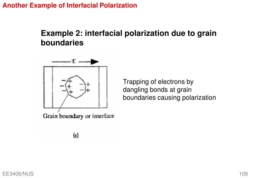
Interfacial polarization, on the other hand, is a sneaky beast. It doesn’t rely on molecules rotating. It relies on charges getting trapped. This happens at boundaries—grain boundaries, interfaces between different materials, or even inclusions of one phase inside another. Charges pile up, creating a local field that acts like a giant, sluggish dipole. This is why we often call it space charge polarization or the Maxwell-Wagner effect.
Look—if you’re working with pure, homogeneous liquids or gases, you’re mostly dealing with orientational effects. But the moment you introduce solid impurities, layered structures, or even a bit of moisture, interfacial polarization can dominate your dielectric response. It’s a big deal.
Orientational Polarization: The Dipole Tango
For orientational polarization, the key player is the permanent dipole moment. These are molecules that already have a charge imbalance, like a tiny magnet with north and south poles. When you turn on the electric field, they try to twist and point in the same direction.
This isn’t instantaneous. It takes time. The relaxation time here is usually in the picosecond to nanosecond range for most small molecules in a liquid. Why? Because the molecule has to physically rotate through the viscous drag of its neighbors. Think of it like spinning a pencil in honey versus air. The thicker the medium, the slower the rotation.
Here’s a practical reality: this mechanism is highly dependent on temperature. Warm up a polar liquid, and the molecules have more thermal energy to overcome that viscous drag. They align faster. But if you get too hot, the thermal motion becomes so violent that they can’t stay aligned at all. You lose the polarization. It’s a delicate balance.
Where do you see this in real life? Everywhere. The dielectric properties of transformer oil, the insulation in your refrigerator, the behavior of water at microwave frequencies. The famous Debye relaxation model was built to describe this exact process. And it works beautifully—for simple liquids. For solid polymers with polar side groups? It gets messier, but the core idea holds.
Interfacial Polarization: The Charge Prisoner
Now, let’s talk about interfacial polarization. This one feels more like a crime scene. You have mobile charge carriers—electrons, ions, holes—that are happily drifting through the material under the applied field. Then they hit a barrier. A grain boundary. A polymer interface. A tiny void. Suddenly, they’re stuck.
These trapped charges build up. They form a macroscopic dipole layer across the interface. The effect mimics a capacitor within your capacitor. This is why the Maxwell-Wagner model exists: it treats the material as a series of layers or phases with different conductivities and permittivities.
Here’s the kicker: this process is slow. Seriously slow. Relaxation times can be microseconds, milliseconds, or even seconds. At mains frequency (50 or 60 Hz), interfacial polarization can be very active. At radio frequencies (MHz and above)? Forget it. The charges simply can’t keep up with the field reversal. They get trapped in place, and the polarization vanishes.
This is critical for anyone designing insulation for high-voltage DC systems. Under DC, interfacial polarization has all the time in the world to build up. The resulting space charge can distort the internal field so badly that it causes a breakdown at a voltage far below what the AC rating would suggest. I’ve seen cables that ran fine on AC blow up in minutes under DC. It’s a cheap lesson I learned the hard way.
Why There is No “Winner” – And Why That Makes Engineering Fun
People often ask me which polarization is “better.” The answer is always “It depends.” Seriously. They are tools for different jobs. The interfacial vs orientational polarization differences become tools, not flaws, when you understand the frequency domain.
If you need a high-permittivity material for a capacitor that operates at 50 Hz, you want strong interfacial polarization. Look for composite materials with conductive fillers in an insulating matrix. The interfaces will trap charges and give you a massive permittivity boost. That’s how some high-value ceramic capacitors work.
If you need a material for microwave applications, orientational polarization using a dipole liquid (like specific esters) can give you controlled loss and heating. But you have to carefully tune the relaxation time to match your frequency. If the relaxation peak falls right in your operating band, you’ll get massive dielectric loss and heat. Sometimes that’s good (microwave heating). Sometimes it’s catastrophic (melting your antenna).
The truth is, most real-world materials show both types. A polymer film with polar groups will have orientational polarization from the molecular dipoles. But that same film might have amorphous and crystalline regions with interfaces, leading to additional interfacial polarization. You have to separate the contributions. In my lab, we use broadband dielectric spectroscopy from 1 mHz up to 1 MHz to pull them apart. It’s not glamorous, but it tells you exactly what’s happening.
Frequency Response: The Race Against the Clock
This is where the rubber meets the road. Imagine you sweep the frequency of your applied field from DC up to the gigahertz range. You’ll see distinct steps (or “relaxations”) in the permittivity.
At very low frequencies, both mechanisms are active. The permittivity is high because the large, slow interfacial dipoles can fully respond. As you increase frequency, the interfacial polarization drops off first. The charges can’t hop fast enough. You see a big step down in permittivity. This is often at frequencies below 1 kHz.
Then, as you push into the radio frequency range, the orientational polarization starts to fail. The molecules can’t rotate fast enough to keep up with the field. You see another step down. This is the primary relaxation, often in the MHz to GHz range for small molecules.
What’s left? Electronic and atomic polarization. These are incredibly fast, happening at optical frequencies. They are the reason glass is transparent but still has a refractive index.
The slope of the relaxation curve, the height of the step, and the exact frequency tell you everything about the material. A sharp step means a single, well-defined relaxation time (simple orientational process). A broad, smeared-out step means a distribution of relaxation times—often a sign of interfacial processes in a disordered material.
Practical Implications: From Capacitors to Cable Insulation
Let’s get concrete. I do a lot of work with high-voltage bushings. These are basically big insulators that let a conductor pass through a grounded wall. They use oil-impregnated paper.
The paper is a porous material. The oil fills the pores. At the water-oil interface? You get massive interfacial polarization. This is actually a problem. The trapped charges at those interfaces can cause partial discharge, eroding the paper over time. We design these things with very specific oil viscosity and paper density to push the interfacial relaxation into a frequency range where it’s less destructive.
For a capacitor designer, it’s the opposite game. You want huge interfacial polarization to boost the capacitance. Use a material like barium titanate (a ferroelectric ceramic) with engineered grain boundaries. The polarization at the boundaries is monstrous—permittivities in the thousands. But that only works at low frequencies. Put that same capacitor in a decoupling circuit for a 5 GHz signal, and it behaves like a simple resistor. The orientation and interfacial mechanisms are both completely gone.
Here’s a quick cheat sheet from my field notes:
- Orientational polarization is molecule-centric, fast (ns-ps), and temperature sensitive. It’s dominant in pure polar liquids and some solid polymers.
- Interfacial polarization is charge-centric, slow (ms-s), and structure sensitive. It’s dominant in heterogeneous solids, composites, and impure systems.
- Both are frequency dependent. You can’t assume one is present without data.
- Loss (tan delta) peaks are your friend. A peak at a certain frequency tells you that the polarization mechanism is “resonating” with the field there.
A Quick Cheat Sheet for the Lab
I know you want the no-nonsense comparison. Here’s how I explain it to my junior engineers. It’s not in the textbooks, but it works:
- If it’s a homogeneous liquid or polymer with a dipole moment, start with orientational polarization models. Debye, Cole-Cole, Havriliak-Negami. These are your tools.
- If the material has visible phases, layers, fillers, or is a composite, assume interfacial polarization is present. Use Maxwell-Wagner or a percolation model. Don’t ignore it.
- If your frequency is under 1 kHz, interfacial polarization is almost certainly a factor. Above 10 MHz, it’s almost certainly not.
- If you see a huge dielectric constant (over 1000) at low frequency, it’s interfacial, not orientational. Pure dipoles rarely give constants that high without some space charge help.
- If your material fails under DC but passes under AC, blame interfacial polarization. Space charge buildup under DC is the silent killer.
I’ll also say this: don’t be fooled by a “pure” material. Even distilled water has impurities. The moment you put it in a container, you have an interface with the glass or plastic. That’s interfacial polarization right there. The effects are usually small, but if you’re trying to measure the dielectric constant with 0.1% accuracy, that interface makes a real difference.
Common Questions About Interfacial vs Orientational Polarization Differences
Which polarization mechanism is faster?
Orientational polarization is generally much faster, with relaxation times in the picosecond to nanosecond range. Interfacial polarization is slow, often in the microsecond to second range. This is the fundamental interfacial vs orientational polarization differences in terms of speed.
Can both types of polarization occur in the same material?
Absolutely. In fact, it’s the norm. Most real-world materials, especially solid polymers and composites, show both. A semicrystalline polymer like PET has dipoles in the amorphous phase (orientational) and interfaces between the crystalline and amorphous regions (interfacial). Separating them requires careful frequency and temperature analysis.
Why is interfacial polarization also called Maxwell-Wagner polarization?
Because the mathematical model for it was first developed in detail by James Clerk Maxwell and then expanded upon by Karl Willy Wagner. They described how charge builds up at the interface between two materials with different conductivities and permittivities. So, when you hear “Maxwell-Wagner effect,” they’re talking about interfacial polarization.
Does temperature affect these two mechanisms differently?
Yes, significantly. Orientational polarization is heavily influenced by molecular mobility, which increases with temperature. Higher temperature usually speeds up the relaxation time (shifts it to higher frequency). Interfacial polarization is also temperature dependent, but more through the conductivity of the materials. Charge carriers become more mobile with heat, which can either enhance or suppress the space charge buildup depending on the specific system. It’s a more complex relationship.
How can I measure which one is dominant in my sample?
You need broadband dielectric spectroscopy. Measure the complex permittivity (real and imaginary parts) over a wide frequency range, typically from 0.001 Hz to 1 MHz or higher. Plot the data. Look for distinct relaxation steps or peaks. A peak at low frequency (<1 kHz) with a large amplitude suggests interfacial polarization. A peak at higher frequency (kHz to MHz) with a lower amplitude suggests orientational polarization. The shape of the peak also gives clues—broad peaks often point to a distribution of interfacial processes. There is no shortcut, you need the data.