
Using a Diode to Protect Against Reverse Bias Damage: The Expert's Guide
I once watched a $3,000 industrial controller smoke itself into oblivion because someone hooked up a 24V power supply backwards. The smell was unmistakable—that acrid, burnt-electronics aroma that means you're about to spend a Friday evening troubleshooting instead of heading home. And the worst part? A single $0.20 diode could have saved the whole board. Honestly, that's the kind of lesson that sticks with you. If you're designing any circuit that plugs into a power source, protecting against reverse bias damage isn't optional—it's survival. So let's talk about how a humble piece of silicon can be your circuit's best friend.
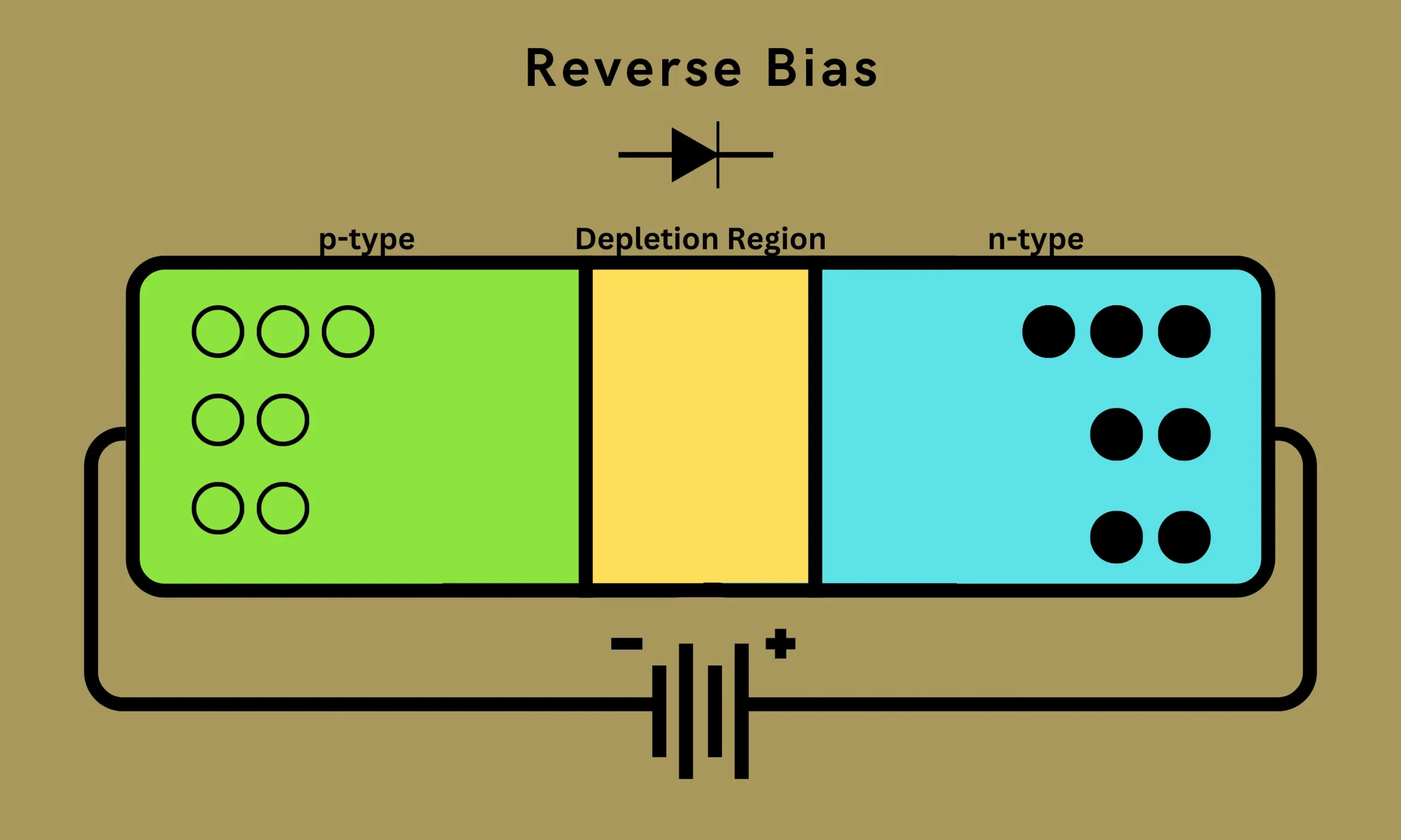
Why Reverse Bias Wrecks Your Circuit (and Why You Should Care)
Reverse bias happens when you accidentally connect the positive supply to the ground rail and the negative supply to the power rail. It's easier to do than you think—especially in battery-powered devices, automotive systems, or any project where someone (maybe even you) plugs in a connector backwards. The result? Current flows in the wrong direction through your sensitive components. Integrated circuits, electrolytics, and microcontrollers aren't exactly fans of this treatment. They tend to release their magic smoke, and that smoke doesn't go back in.
When reverse bias hits, the parasitic diodes inside your ICs can forward-bias and dump massive current where it shouldn't go. Traces vaporize. Chips latch up and fry. Capacitors explode (yes, really—it's loud and messy). The damage isn't always instant, either. Sometimes it's a slow death: a chip that works intermittently for weeks before finally giving up. That's the insidious kind of failure that makes you question your own sanity as an engineer. Protecting against reverse bias damage isn't just about preventing the dramatic meltdown—it's about reliability over the long haul.
Here's the thing: most people think "oh, I'll just be careful when I plug it in." No. You won't. Look—I've been doing this for over a decade. I've seen PhD-level engineers blow up prototypes because they were tired and grabbed the wrong cable. It happens. Plan for it.
There are two main approaches to reverse polarity protection: the shunt diode method and the series P-channel MOSFET method. We'll start with the classic, because it's elegant, cheap, and teaches you all the fundamental principles you need to know.
The Classic Solution: Shunt Diode Reverse Polarity Protection
The concept is dead simple. You place a diode (typically a Schottky or a standard silicon rectifier) in parallel with your load, but connected in reverse—cathode to positive rail, anode to ground. Under normal operation, the diode is reverse-biased and blocks current. It's essentially invisible to your circuit, except for a tiny bit of leakage current (which we'll talk about in a minute). When reverse polarity hits, the diode becomes forward-biased and conducts like a champ. It shorts the reverse voltage, creating a low-impedance path that blows the upstream fuse or trips the PTC resettable fuse. The key here is that the diode sacrifices itself (or rather, the fuse does) to save your expensive downstream components.
But here's where the gotchas live. You can't just grab any old diode and call it a day. The reverse bias protection effectiveness depends entirely on choosing the right diode for your current and voltage. If you're protecting a circuit that draws 5 amps, you need a diode rated for at least 7.5 to 10 amps (derating is your friend). The reverse voltage rating should be at least 1.5 times your maximum supply voltage. And the forward voltage drop—this is a big one—determines how much current the diode can handle during the fault condition without melting.
A common mistake is using a 1N4007 (1 amp rated) on a circuit that can pull 2 amps during the reverse fault. That diode will heat up faster than a cheap soldering iron. It might even fail short, which then defeats the entire purpose of the protection. Seriously, I've seen this happen. The diode dies, and now the reverse voltage has an even easier path to your load. Not good.
The Hidden Voltage Penalty Nobody Talks About
This is the part that catches most hobbyists and even some seasoned pros off guard. The shunt diode approach has a significant downside during normal operation: it does absolutely nothing to your supply rail while everything is happy. That's great—no voltage drop, no power loss. But the moment a reverse polarity event occurs, the diode conducts heavily and you lose the entire supply voltage across the fuse. If your fuse is slow to blow (which many are), your circuit might experience a brief but brutal reverse voltage spike before the protection kicks in.
Here's a practical tip I've learned the hard way: pair your shunt diode with a fast-acting fuse or a PTC resettable fuse. Don't rely on a slow-blow fuse that takes 500 milliseconds to clear. By then, your microcontroller is already dead. Use a fuse with an I²t rating that matches the diode's surge current capability. And place the diode as close physically to the power input connector as possible. Those long traces can act like antennas and create enough inductance to delay the diode turning on. We're talking nanoseconds here, but in modern high-speed circuits, nanoseconds matter.
Another hidden issue: the shunt diode will draw a significant surge current when the reverse voltage is applied. That surge can cause your power supply (if it's a lab bench supply, for example) to go into current limit or even shut down. In automotive systems, that surge can cause transients on the 12V line that confuse other ECUs. It's a solvable problem—just oversize the diode and the fuse—but it's not a "set it and forget it" solution.
Honestly? For low-power circuits under 1 amp, the shunt diode method is still my go-to. It's cheap, it's simple, and it works. But for anything above that, you might want to consider the MOSFET option we'll get to next.
The Smarter Alternative: Using a P-Channel MOSFET for Active Protection
If the shunt diode is the old-school hammer, the P-channel MOSFET is the precision screwdriver. It avoids the voltage drop problem entirely because the MOSFET has a very low RDS(on)—typically in the milliohm range. This means you don't lose any voltage during normal operation. No heat, no efficiency losses. For battery-powered devices, this is a huge win.
The configuration is simple: you place a P-channel MOSFET in series with the positive supply rail, with the source connected to the input and the drain connected to the load. The gate is connected to ground through a resistor (usually 10kΩ to 100kΩ). In normal polarity, the gate is at ground, the source is at Vin, so the gate-to-source voltage (VGS) is negative—which turns the MOSFET on. When reverse polarity hits, the source is now at ground potential, the gate is still pulled low, and VGS becomes zero or positive, turning the MOSFET off and blocking the reverse current. No fuse needed, no voltage drop, no muss.
But here's the catch: the MOSFET's body diode is forward-biased during reverse polarity. If the reverse voltage exceeds the diode's rating, you can still get current flow through the body diode. To prevent that, you either use a MOSFET with a robust body diode or add a Schottky diode in series with the drain. Some designers also use an N-channel MOSFET on the ground side (low-side protection) to eliminate the body diode issue entirely. It's a trade-off.
Look—I'll be honest: I've had mixed results with the simple P-channel implementation. The gate protection circuitry can be tricky, especially in noisy environments like automotive. If the gate voltage ever goes above the source voltage (transients, ESD, etc.), the MOSFET can turn on when it shouldn't. That's why I always add a zener diode from gate to source (cat node to gate, anode to source) to clamp the gate voltage. And a series resistor between the gate and the pull-down resistor to limit current. It adds two components, but it saves you from unexpected failures.
How to Choose the Right P-Channel MOSFET
Picking the wrong MOSFET is like bringing a knife to a gunfight. You need to look at several critical parameters. The first is VGS(th)—the gate threshold voltage. It needs to be low enough that your input voltage can reliably turn the MOSFET on. For a 5V system, you want a MOSFET with a VGS(th) of 1V to 2V max. For 3.3V, you need a logic-level MOSFET with a threshold below 1V. If you use a standard MOSFET with a 3V threshold on a 3.3V rail, you might get marginal turn-on, which means higher resistance and more heat.
Reverse bias protection using a MOSFET isn't just about turning off during fault. It's also about surviving the fault without damage. The MOSFET's maximum drain-to-source voltage (VDSS) must exceed the reverse supply voltage by a healthy margin. And the continuous drain current rating (ID) must handle your normal load plus any inrush. I typically derate by 50% for temperature and surge conditions.
Here's a quick checklist I use when evaluating a P-channel MOSFET for reverse polarity protection:
- Low RDS(on) (under 50mΩ for most applications) to minimize heat and voltage drop.
- Low VGS(th) (ideally under 1.5V) for 3.3V and 5V systems.
- High VDSS rating (at least 30V for automotive, 20V for general use).
- Robust body diode with high surge current capability (check the datasheet for IFSM).
- Gate protection included internally (some MOSFETs have built-in zener clamps—look for those).
The thermal performance is often overlooked. A MOSFET in a SOT-23 package can handle maybe 1-2 watts before it's in trouble. If you're passing 3 amps through a 30mΩ device, that's 0.27W—fine for a larger package like DPAK or D2PAK, but too much for a tiny surface-mount device. Always do the thermal math.
Real-World Caveats and Practical Tricks
One thing that drives me crazy is when people forget about the load capacitance. If you have a large capacitor on the output (say, 1000µF), the inrush current when you first connect power can be massive. That inrush can momentarily exceed the MOSFET's safe operating area (SOA) and damage it. The solution is to add a soft-start circuit—a small resistor and capacitor on the gate to slow down the turn-on. Or you can use a hot-swap controller IC that handles all this automatically. But for a simple reverse polarity protection circuit, just add a series resistor between the input and the MOSFET drain (like a 1Ω to 10Ω, rated for surge) to limit the inrush. It's not elegant, but it works.
Another gotcha: the gate pull-down resistor. If the input is connected but the gate resistor is open (bad solder joint, damaged trace), the gate floats. That can cause the MOSFET to operate in the linear region—partially on, generating massive heat, and eventually failing. Always verify that your gate resistor is physically intact during board inspection. I learned this the expensive way during a production run of 500 units.
And here's a completely unexpected benefit of the MOSFET approach: it can double as a load switch. With a small control signal to the gate (through an NPN transistor or a logic level shifter), you can turn your entire circuit on and off. That's a handy feature if you're building a low-power device that needs to cut power to save battery. The reverse polarity protection is always active, but you get an extra function for free.
When You Absolutely Should Use a Diode (and When You Shouldn't)
Let's be real: there's no single perfect solution for every scenario. The shunt diode method is unbeatable for simplicity and cost. If your circuit draws less than 500mA, a Schottky diode like the 1N5819 or SS34 will work beautifully. You don't need to worry about gate drive circuits, threshold voltages, or soft-start. It just works. For higher currents (2A or more), the forward voltage drop of a Schottky becomes a problem—you're losing 0.4V to 0.6V, which at 5A means 2 to 3 watts of heat. That's a lot to dissipate. In those cases, the MOSFET is the better choice.
There's also the question of speed. A diode can react to a reverse polarity event in nanoseconds. A MOSFET depends on the gate drive circuit, which can have delays. If your application involves hot-plugging connectors that can momentarily reverse polarity during mating (common in some automotive and industrial connectors), the diode's speed might be an advantage. But honestly, in most real-world scenarios, both approaches are fast enough.
Here's a scenario where I always reach for a diode: when I'm prototyping on a breadboard. It's quick, it's forgiving, and you can swap it out in seconds. MOSFETs are more finicky on breadboards because of the stray capacitance and the gate's sensitivity to noise. I've seen many a prototype fail because the MOSFET self-oscillated due to poor layout. Not fun to debug.
And here's a scenario where I never use a diode: high-efficiency, battery-operated devices. Every millivolt of drop matters. A diode wastes energy as heat. A MOSFET wastes almost nothing. For a device that runs on a single lithium cell (3.7V nominal), losing 0.4V across a diode means you're losing about 10% of your available power. That's unacceptable. Use the MOSFET.
Common Questions About Using a Diode to Protect Against Reverse Bias Damage
What type of diode is best for reverse polarity protection?
For low-voltage applications (under 30V), a Schottky diode like the 1N5819 or SS34 is ideal because of its low forward voltage drop (typically 0.3V to 0.5V at rated current). For higher voltages (above 100V), you need a fast recovery diode because standard silicon rectifiers have slow recovery times that can cause issues during fault transients. Always check the reverse voltage rating—it must exceed your maximum supply voltage plus a safety margin of at least 20%. And consider the surge current capability (IFSM) if your application has large capacitors that create inrush.
Can I use a regular silicon diode like the 1N4007 for reverse bias protection?
You can, but I wouldn't recommend it for most modern circuits. The 1N4007 has a forward voltage drop of about 1.1V at 1A, which is high enough to cause significant power loss and heat. It also has a slow recovery time (microseconds) that can be problematic in circuits with high-frequency switching noise. For low-current, low-voltage hobby projects, it'll work, but for any serious design, use a Schottky. The 1N4007 is fine as a last-resort if that's all you have on hand, but upgrade as soon as you can.
Does a series diode (on the positive rail) also protect against reverse bias?
Yes, a series diode placed in line with the positive supply rail (cathode to load, anode to input) will block reverse current entirely. It's a simpler and more foolproof approach than the shunt method because no fuse is required—the diode just blocks reverse voltage outright. The downside is that you incur the forward voltage drop during normal operation, which wastes power. It's a trade-off. This is often called a "blocking diode" and is common in automotive and solar applications where simplicity matters more than efficiency.
How do I protect a circuit that uses both positive and negative supplies?
This is where things get spicy. You need a diode on each supply rail, oriented correctly. On the positive rail, the diode's cathode goes to the load (blocking reverse current from the positive rail). On the negative rail, the diode's anode goes to the load (blocking reverse current from the negative rail). You also need a fuse on the positive rail for overcurrent protection. This is common in operational amplifier circuits and audio gear. I've designed this into several precision measurement instruments, and it works perfectly—just watch the voltage drops from each diode, because they add up and can affect the supply voltage seen by your op-amps.
What about using a TVS diode instead of a standard diode for reverse bias protection?
A TVS (transient voltage suppression) diode is designed to clamp voltage spikes, not to conduct continuous reverse current. Using a TVS as a reverse polarity protection device will likely destroy it—they aren't rated for the sustained current that occurs when you accidentally connect power backwards. A TVS can be used in parallel with your standard protection diode to provide surge suppression, but don't rely on it alone. The standard Schottky or silicon rectifier is the right tool for this job.
At the end of the day, using a diode to protect against reverse bias damage is one of the most cost-effective reliability moves you can make. It's not glamorous. It's not complicated. But it separates the designs that survive the real world from the ones that become expensive paperweights. Pick your diode wisely, derate it properly.
The correct form is using. This confusion happens to students, bloggers, professionals, and even native english speakers. Is it “useing” or “using”? The fact or state of being used Like const, variables declared with using must be initialized and cannot be reassigned. This violates the rule that the material preceding the colon must be a complete thought. Application put knowledge to use b : Apakah anda sering bingung antara penggunaan kata use dan using dalam bahasa inggris? Present participle of use 2. Use dan using adalah dua kata dalam bahasa inggris yang seringkali membingungkan banyak orang.