
Open Circuit vs Closed Circuit Voltage Drops: The Silent Truth About Your Measurements
I remember sitting in my first serious diagnostics class, staring at a marine battery that read a perfect 12.6 volts on my meter. The student next to me was pulling his hair out because the starter wouldn't crank. We both measured the same open circuit voltage. We both got the same number. His system was dead. Mine worked fine. That's the moment the difference between open circuit voltage vs closed circuit voltage drops stopped being a textbook concept and became a practical obsession for me. Seriously, if you only measure batteries at rest, you're flying blind.
Understanding the gap between these two measurements is the difference between swapping parts randomly and actually fixing the problem. It's a big deal. Many technicians—even seasoned ones—get tripped up here because they trust that static reading too much. Look—a voltage drop isn't something that just happens in a failing component. It's a fundamental law of physics playing out right under your test leads. And once you grasp it, you'll never look at a multimeter the same way again.
We're going to tear this apart. No fluff. Just the real-world behavior of electrons when the circuit is open, versus when it's loaded down and working. We'll talk about why that 12.6 volts can instantly drop to 10 volts the moment you hit the start button, and what that actually tells you about the health of your battery, your wires, and your connections. Honesty? This is the single most useful skill I've used in a decade of field work.
The Silent Truth About Voltage: It's All About Load
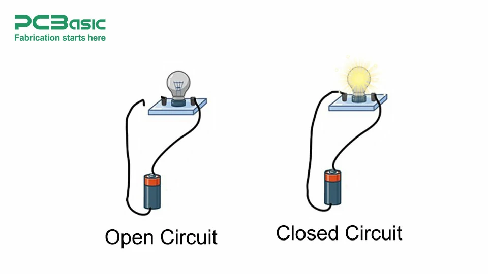
Think of voltage as electrical pressure. Open circuit voltage is the pressure in a pipe with the valve closed. The source is there, the potential is real, but no water is flowing. You measure it across the terminals of a battery that isn't connected to anything, or across a switch that's turned off. It's the theoretical maximum. It's easy to measure. And it's often misleading.
A battery can show a beautiful open circuit voltage of 12.6V and still be completely destroyed internally. I've tested batteries that showed perfect standing voltage but collapsed to under 9V under a simple headlight load. That's the dirty secret. Closed circuit voltage drop is the real-world pressure remaining after current is flowing through a load and everything else in the path. It's the measured voltage across a component or a connection while the circuit is active and doing work.
The difference between these two numbers tells you the health of the entire system. If the closed circuit voltage is significantly lower than the open circuit voltage, you have excessive resistance somewhere. It could be a corroded terminal, a wire that's partially broken, or a failing battery. Measuring just the open voltage is like checking if a car has fuel in the tank but never checking if the fuel line is clogged.
Let me give you a hard truth. Many professionals call a 'voltage drop test' without clarifying it's a closed-circuit test. A true voltage drop test, the kind that finds bad connections, MUST be done under load. Doing it on an open circuit gives you almost zero useful data. It's a static reading of potential, not performance.
Why Your Multimeter Lies to You on Open Circuit
Your digital multimeter (DMM) has an incredibly high input impedance, typically 10 megohms. That means when you probe an open circuit, the meter itself draws almost zero current. It's a ghost load. It perfectly reads the source voltage because there's no resistance in the path to drop any pressure. The battery doesn't care. The wire doesn't care. Everything is perfect because nothing is working.
This is why you can measure 12.6V at the battery, then measure 12.6V at the back of a starter solenoid that's connected through a rusty, corroded cable. The meter sees the full voltage because the path isn't loaded. It's like measuring the water pressure at the city main with a tiny straw—you'll get full pressure because the straw can't flow enough water to create a drop.
As soon as you close the circuit and ask for 100 amps to crank an engine, that same rusty cable becomes a bottleneck. The voltage that was 12.6V at the solenoid terminal might instantly drop to 9V because the resistance in the cable is eating up 3.6V of pressure. The open circuit voltage didn't warn you. The meter didn't lie—it just showed you what you asked for, which was nothing useful.
So, rule number one in my book: Never trust a standing voltage reading as proof that a circuit is healthy. Use it only as a baseline to compare against your closed circuit voltage drop numbers. The difference is the truth.
The Physics of a Loaded Circuit: Where the Voltage Goes
When you close the switch and current starts to flow, Ohm's Law takes over. Voltage equals current times resistance (V = I x R). Every single piece of the circuit—the wire, the connectors, the switch contacts, the ground path—has some resistance, even if it's only 0.001 ohms. When current flows through that resistance, a voltage drop occurs. The source voltage gets divided up among all these resistances.
This is why a proper voltage drop test is the gold standard. You measure the voltage across a specific connection or cable while the circuit is fully loaded. For example, with the starter cranking, you put your meter leads on the battery positive post and the starter positive terminal. If you read 0.5V, that means the positive cable is dropping half a volt. That's bad. It means energy is being wasted as heat in that cable instead of reaching the starter motor.
Compare that to an open circuit voltage measurement across the same two points. You'd read 0V because no current is flowing and no voltage is being 'used up' by the cable's resistance. The cable is just a wire waiting to fail. The closed circuit voltage drop exposes that weakness immediately. It's the difference between knowing a wire is there and knowing it can do its job.
In my experience, the most common failure points are the ground connections. A battery can have perfect open circuit voltage at the positive terminal, but a bad ground cable will create a massive voltage drop under load, starving the starter or headlights. Always test the ground side under load. It's the path most overlooked.
Practical Bench Test: Seeing the Difference Live
I want you to visualize this because it's the fastest way to lock this concept in your head. Imagine a simple circuit: a 12V battery, a long thin wire (let's say it has 0.5 ohms of resistance), and a 6-ohm light bulb. On an open circuit, you probe across the battery terminals. You see 12.6V. Perfect open circuit voltage.
Now, close the switch. The bulb lights up. Measure across the battery terminals again under this closed circuit condition. The battery voltage might drop slightly to 12.4V due to internal resistance. That's normal. But now measure across the long thin wire (from battery positive to the bulb's positive terminal). You might see a voltage drop of nearly 1 volt! The wire is stealing that energy. The closed circuit voltage measured across the bulb is now only 11.4V.
This is the core of the problem. The open circuit voltage you measured first was 12.6V. The voltage drop across the wire is 1V. The closed circuit voltage available for the bulb is only 11.4V. Your '12V' system is not delivering 12V to the load. It's delivering 11.4V. If this wire was in your car, the light would be dimmer, the starter would crank slower, and you'd be wondering what's wrong.
Here is a checklist I use on every single diagnostics job:
- Open Circuit Voltage Check: Baseline reading at the source. Confirms the battery or power supply is theoretically alive.
- Closed Circuit Voltage Check: Measure at the load while it's running. Confirm the load is getting usable voltage.
- Voltage Drop Test (Cable Side): Measure from source terminal to load terminal under full load. Should be less than 0.1V for high-current circuits, 0.5V max for lighting.
- Voltage Drop Test (Ground Side): Measure from load ground to battery negative under load. Same rules. This catches the 'hidden' resistance.
Using an Ohmmeter vs. a Voltmeter: The Wrong and Right Tool
Some techs reach for an ohmmeter to check for resistance in a cable. Bad idea. A standard ohmmeter uses a tiny current to measure resistance. It cannot stress a connection like a real load does. A corroded connection might measure 0.2 ohms on an ohmmeter (which seems fine) but under 50 amps of load, it could drop 4 volts.
The voltage drop test with a voltmeter under load is the only reliable method. It uses the circuit's own current to reveal the problem. It doesn't lie. A reading of 0.5V across a ground cable under a cranking load is an immediate red flag. You don't need to calculate resistance—just see the pressure loss. It's practical and fast.
I once spent an hour chasing a parasitic draw. The open circuit voltage was perfect. The battery passed a load test. But the car died overnight. I finally did a closed circuit voltage drop across every fuse. Found a 2.5mV drop across a 20A fuse. Normal circuits were dropping under 1mV. Chased that tiny drop to a glovebox light staying on. That voltage drop under the minimal load of the meter current was the only clue. Open circuit showed nothing.
The bottom line? An ohmmeter shows you potential resistance. A voltmeter under load shows you actual performance. Trust the load test every single time.
Why Your Car Battery Fails the Cranking Test (And Your Meter Doesn't)
This is the most common scenario I see in driveways and shops. Customer says, "My battery is good. I checked it with my meter. It reads 12.6 volts." Then the car won't start. The issue is they only checked open circuit voltage. A battery can have perfect surface charge and zero capacity. An old, sulfated battery can hold a standing voltage but collapses internally the moment you demand 200 cranking amps.
When you load the battery (close the circuit), the closed circuit voltage at the battery terminals drops. A healthy battery at room temperature might drop to 10.5V for a few seconds during cranking. A bad battery might drop to 7V. You can't see that unless you measure under load. This is why professional load testers carbon-pile or conductance testers are essential. They simulate the load.
You can do a poor man's load test with headlights. Turn them on for 30 seconds (to burn off surface charge), then measure the closed circuit voltage at the battery. If it's below 12.0V while the lights are on, the battery is suspect. If you then try to crank and the voltage plummets below 9.5V, the battery is done. The open circuit voltage was a lie.
Here are the critical thresholds I use based on years of field data:
- Open Circuit Voltage (Resting, 12h after charge):
- 12.6V+ fully charged.
- 12.4V ~75% charged.
- 12.2V ~50% charged.
- Below 12.0V discharged or damaged.
- Closed Circuit Voltage (Under Cranking Load):
- Above 10.5V excellent battery health.
- 9.5V to 10.5V acceptable, but aging.
- Below 9.5V battery is failing or insufficient capacity for the engine.
- Voltage Drop on Connections (Under Load):
- Below 0.1V excellent.
- 0.1V to 0.3V acceptable for high-current.
- Above 0.5V immediate repair needed.
The Hidden Enemy: Contact Resistance and Corrosion
Voltage drop isn't just about long wires or bad batteries. It's often about microscopic corrosion at a terminal, a slightly loose nut, or a dirty relay contact. These create high-resistance points that only show up under load. I've fixed hundreds of 'no-start' issues by simply cleaning a battery terminal. The open circuit voltage was always perfect. The closed circuit voltage drop across that dirty terminal was 1.5 volts.
Think about a relay. You check the coil resistance on an open circuit. It reads 80 ohms. Fine. But the contacts inside are pitted. The voltage drop across those closed contacts under load might be 0.8V instead of 0.0V. That 0.8V means the load isn't getting full power. The relay passes a resistance check but fails a performance check. You only find this with a closed circuit voltage drop test.
This is where your skill as a technician separates from a parts swapper. Measuring voltage drop requires interpreting the numbers in context. A 0.3V drop on a starter cable is bad. A 0.3V drop on a fuel pump circuit might be acceptable. You learn these tolerances by doing and by knowing the expected current draw of the circuit. Experience is the key that unlocks the data.
Common Questions About Open Circuit vs Closed Circuit Voltage Drops
Why does open circuit voltage stay the same even with bad connections?
Because no current is flowing. Voltage is measured in parallel across two points. If there is a high resistance connection (like corrosion), and zero current is passing through it, there is no voltage drop across that resistance. Ohm's Law (V=I*R) says if I is zero, V is zero. So the full source voltage appears on both sides of the bad connection. Your meter sees the source voltage, not the problem. The resistance only becomes apparent when current flows, creating a measurable voltage drop.
Is a voltage drop test always done on a closed circuit?
Yes, for it to be valid, the circuit must be operating under its normal load or a simulated load. You cannot measure the effect of a bad connection on an open circuit. The term "voltage drop test" in professional diagnostics always implies a closed circuit measurement. Measuring across a open switch gives you source voltage, which tells you nothing about the switch's condition when closed.
What is the normal voltage drop for a starter circuit?
For a 12V starter circuit drawing 150-200 amps, you want a total voltage drop from battery positive to starter terminal, plus from starter case to battery negative, to be under 0.5V. Ideally, under 0.2V. Each individual connection (cable lug, solenoid stud) should show under 0.1V. If you see anything above 0.3V on a single cable, clean or replace it. Higher resistance means wasted energy and slower cranking.
Can a bad ground cause high closed circuit voltage drop?
Absolutely. In fact, bad grounds are the most common cause of mysterious electrical problems. A poor ground connection creates resistance in the return path. This forces the current to find alternative paths (like through sensors or other modules), causing erratic behavior. Measuring the voltage drop from the load's ground terminal to the battery negative terminal under load will expose this immediately.
How do I measure closed circuit voltage drop accurately?
Set your DMM to DC volts. Connect the red lead to the side of the connection closer to the positive source. Connect the black lead to the side closer to the load or ground. Apply the full load to the circuit (crank the engine, turn on the lights, engage the motor). Read the display. That number is the voltage drop across that specific part of the circuit. A reading of 0.1V or less is excellent. Higher indicates resistance.