
Step-by-Step Guide to Measuring Reverse Bias State with a Multimeter
I’ve lost count of how many times I’ve watched someone yank a diode out of a circuit board, toss it into a drawer labeled “maybe good,” and move on without ever checking the one measurement that actually tells you if the part is toast. You can measure forward voltage until the cows come home, but if you ignore the reverse bias state, you are flying blind. Seriously. I’ve seen brand-new-looking diodes that pass the forward test with flying colors but leak like a sieve in reverse. That leak will kill your power supply, your driver circuit, or your precious audio amplifier dead in the water. So let’s fix that.
Look—I’ve been doing this for over a decade. I’ve blown up my own multimeter probes (yes, actually melted the tips), and I’ve learned the hard way that measuring reverse bias is not just slapping two probes across a part. It requires a tiny bit of setup, a tiny bit of understanding, and a whole lot of attention to what the meter actually tells you. This step-by-step guide will get you there.
Understanding What Reverse Bias Really Means (And Why Your Multimeter Can Test It)
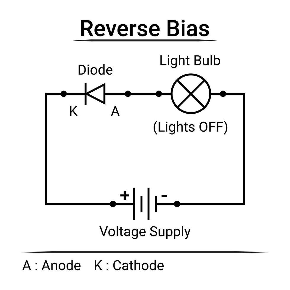
Before you even touch the probes, you need to understand what your multimeter is trying to do when it measures reverse bias. This isn’t just academic jargon. It's the difference between a working circuit and a repair that fails ten minutes later. Reverse bias refers to the condition where the positive voltage is applied to the cathode of a diode and the negative voltage is applied to the anode. In theory, under perfect reverse bias, a diode should behave like an open circuit. No current flow. Zero. Zip. Measuring reverse bias state with a multimeter essentially checks whether the diode is holding that line under voltage stress.
The Difference Between Diode Mode and Resistance Mode
Here is where most people screw up. They switch the multimeter to resistance mode (ohms) and expect to see infinite resistance in reverse. It sort of works, but it’s unreliable. Why? Because resistance mode uses a very low test voltage—often less than a volt. A leaky diode might not show leakage at 0.5 volts but will start conducting at 5 volts. And your multimeter’s diode mode? It usually uses a constant current source that produces a higher voltage across the junction, typically around 2 to 3 volts for most meters. That higher voltage is enough to stress the junction and reveal leakage currents that the resistance mode would completely miss. Measuring the reverse bias state demands that higher test voltage. Don't skip this.
What the Multimeter Actually Sends Into the Diode
When you select diode mode (the little diode symbol or the arrow with a bar), your multimeter sources a constant current—usually about 1 milliampere—and measures the voltage drop across the junction. In forward bias, that gives you a reading around 0.6 volts for silicon. In reverse bias, the current cannot flow, so the voltage across the junction rises until it hits the meter's compliance voltage. That's your multimeter's internal power supply limit, typically between 2.5 and 3.5 volts. If the diode is good, the meter will show “OL” or “1” indicating an open circuit. If it shows any voltage reading below that—like 0.2V, 0.8V, or even 1.2V—you've got a leaky diode. It’s a big deal.
Honestly? Most people get this wrong because they assume “OL” means a broken connection. In reverse bias, “OL” is exactly what you want.
Step-by-Step Process: Measuring Reverse Bias Like a Pro
Alright, let's get into the meat and potatoes. You’ve got your multimeter, you've got your diode, and you’re ready to test. Follow these steps exactly, and I promise you won't be chasing ghosts.
Step 1: Select Diode Mode (Not Continuity, Not Resistance)
This is non-negotiable. Turn your dial to the diode symbol. If your meter doesn't have a dedicated diode mode—and some cheap meters don't—you are going to struggle. In that case, use the resistance mode at the highest range (usually 2M or 20M ohms), but understand the results will be less reliable. For a proper measurement of reverse bias state, diode mode is the tool. Plug your black lead into COM and your red lead into the VΩmA port. Standard stuff.
Step 2: Identify the Anode and Cathode
You cannot do this blind. The cathode is usually marked with a band on the diode body. The anode is the other end. If you mix them up, you'll be measuring forward bias instead of reverse bias. And yes, I’ve seen people test a diode backwards, get a forward voltage reading of 0.6V, and then declare the part good without ever checking the reverse side. That's a rookie move. For measuring reverse bias, the red probe (positive) goes on the cathode. The black probe (negative) goes on the anode. This is the reverse of your forward test.
Step 3: Connect the Probes and Read the Display
Touch the probes to the diode leads. Hold them steady. Look at the display. A good diode will show “OL” (over limit) or sometimes a very high resistance value if you're using resistance mode. A completely shorted diode will show a very low voltage reading—often 0.0V or near zero. A leaky diode will show a specific voltage drop, like 0.3V or 0.7V, which indicates that current is flowing where it shouldn't.
Here's a quick breakdown of what the numbers mean:
- OL or very high resistance = healthy diode in reverse bias. - 0.0V to 0.1V = shorted diode (totally dead). - 0.2V to 1.5V = leaky diode (replace it). - Fluctuating reading = bad contact or thermally unstable junction (still a red flag).
Step 4: Switch Probes and Confirm Forward Bias
This is a sanity check. After you've recorded the reverse bias reading, reverse the probes. Red on anode, black on cathode. You should get a standard forward voltage reading of around 0.5V to 0.8V for silicon, or about 0.2V to 0.4V for Schottky diodes. If you get OL in both directions, the diode is open and completely dead. If you get a voltage reading in both directions, it’s shorted or leaking heavily. The combination of a good forward reading and a clean reverse OL is the only “pass” condition.
Common Pitfalls and How to Avoid Them (From My Personal Error Log)
I’ve made every mistake on this list. And I’ve probably invented a few new ones along the way. Let me save you some pain.
Why In-Circuit Testing of Reverse Bias is a Nightmare
Testing a diode while it’s still soldered into a circuit board is asking for trouble. Parallel components—resistors, capacitors, other diodes—will mess with your reading. You might see a low reverse voltage that isn’t actually a leaky diode; it could be the parallel resistor pulling the voltage down. Measuring reverse bias state in-circuit is only reliable if you understand the entire circuit around the diode. The rule of thumb? If you get a suspicious reading in reverse bias, desolder one leg of the diode and test it out of circuit. Period.
The Multimeter Battery Can Affect Your Readings
This sounds silly, but a dying battery in your multimeter can reduce the compliance voltage. Instead of pushing 2.8V into the diode in reverse bias, a weak battery might only push 1.5V. A mildly leaky diode that starts conducting at 2V will look perfectly good with a weak battery. Always check your meter’s battery if readings seem inconsistent. I always keep a spare 9V in my tool kit for this exact reason.
Temperature Drift Is Real
Diodes are temperature-sensitive. A hot diode will leak more current in reverse bias than a cold one. If you’ve just pulled a component off a running power supply, wait for it to cool down to room temperature before testing. Otherwise, you might condemn a perfectly good diode that only leaks under heat stress. That said, if it leaks significantly at room temperature, it’s bad. No excuses.
Interpreting the Numbers: When Is a Diode Actually Failed?
This is where experience matters. A borderline reading can drive you crazy if you don’t know the context.
- Silicon diodes: Should show OL in reverse. If you see 0.3V, it’s leaking. Replace it. - Schottky diodes: These are naturally more leaky in reverse than silicon. A tiny bit of leakage is normal, but if you see a voltage drop above 0.15V or a clearly steady reading, something is wrong. - Zener diodes: These are designed to break down at a specific reverse voltage. Measuring reverse bias state on a Zener requires knowing its breakdown voltage. If your meter’s compliance voltage is only 3V, you cannot test a 12V Zener in reverse bias with a standard multimeter. You’ll just see OL and get a false sense of security. In that case, you need a variable power supply or a dedicated Zener tester.
Look—I’ve replaced entire batches of diodes based on a single suspicious reverse bias reading, only to find out later that the circuit had a sneaky capacitor leakage that was fooling my meter. Always double-check. But also, trust the math. If a silicon diode shows any steady voltage below OL in reverse bias, it is compromised. Zero exceptions.
Common Questions About Measuring Reverse Bias State With a Multimeter
What does OL mean when measuring reverse bias?
OL stands for Over Limit. It means the multimeter’s internal voltage cannot forward-bias the diode in the reverse direction, and the resistance is so high that the meter cannot measure it. This is the correct reading for a healthy diode under reverse bias.
Can I test a diode in reverse bias with an analog multimeter?
Absolutely. Analog meters work differently though. Instead of OL, the needle will stay at zero (or near zero) in reverse bias because no current flows. In forward bias, the needle jumps up. Analog meters are actually fantastic for this because you can see the needle’s response in real time.
What if my multimeter doesn't have a diode mode?
You can use the resistance (ohms) mode on the highest range. A good diode in reverse bias will show infinite resistance (OL on a digital meter or no needle movement on an analog meter). Just be aware that the test voltage is low, and you may miss subtle leakage.
Why does my diode show a voltage reading in both directions?
That means the diode is shorted or heavily leaky. A good diode should only conduct in one direction. If you get a reading in both directions—even a small one—replace the diode without hesitation.
Can I measure Zener diode reverse bias with a standard multimeter?
Not reliably if the Zener voltage exceeds your meter’s compliance voltage (usually 3V). A 5V Zener might show a reading, but a 12V Zener will just show OL. You need a power supply that can deliver the Zener’s breakdown voltage to test it properly.