
Understanding Kirchhoffs Voltage Law in Complex Circuits
I spent a solid 8 hours last week chasing a ghost in a power supply design. Voltages were dropping where they shouldn't. Components were getting hot. The scope showed noise, but the math? The math was clean. Turns out, I forgot to account for a voltage drop across a parasitic trace inductance. Kirchhoffs Voltage Law caught the lie.
Look—if you're working with anything more complicated than a flashlight circuit, you need to stop treating KVL like a textbook theory and start using it like a scalpel.
Understanding Kirchhoffs Voltage Law in Complex Circuits isn't just about adding up voltages around a single loop. That's easy. The real magic happens when you have nested loops, dependent sources, and reactive components that shift the phase. Let's get into it.
Why KVL is the Circuit Detective You Didn't Know You Needed
It's Just Conservation of Energy (With a Multimeter)
Seriously, at its heart, Kirchhoffs Voltage Law is just saying, "What goes around comes around." Energy cannot be created or destroyed in a closed loop. So, if you start at a point, walk around the circuit, and end up back at the same point, the net change in electrical potential has to be zero.
Think of it like hiking a mountain loop trail. You gain 500 meters of elevation climbing, but you lose exactly 500 meters coming down. If you didn't, you'd be floating. Your circuit feels the same way about electrons.
In a simple DC circuit, it feels trivial. Battery is 9V, resistor drops 9V. Done. But when you have three resistors, a diode, and an inductor all in different orientations, the sign conventions get ugly fast. This is where most engineers trip up. They forget the passive sign convention. If current enters the positive terminal of a component, it's a voltage drop. If it enters the negative terminal, it's a rise.
Without this discipline, your sum around the loop won't equal zero. It will equal a headache.
Here's a quick checklist for applying the passive sign convention correctly:
- Assign a current direction (clockwise is standard practice). - Mark the positive terminal of each component as the one where current enters. - Write the voltage drop as positive when traversing from + to -. - Write the voltage rise as positive when traversing from - to +.
Seriously, that last point alone can save hours of debugging.
Polarity: The Make-or-Break Detail for KVL
I cannot stress this enough. Polarity isn't just a detail; it's the entire game. When you are applying Kirchhoffs Voltage Law to a complex circuit, you have to assign current directions arbitrarily. Yes, arbitrarily.
Let's say you guess the current goes clockwise. You write your equation. You solve it. If the current value comes out negative, you just guessed wrong. No big deal. The magnitude is correct, and the sign tells you the actual direction.
The mistake people make? They switch polarities mid-loop to make the math "feel" right. Don't do that. Consistency over intuition. Write the equation, trust the math, fix the sign later. Honestly, this one habit separates hobbyists from pros.
Understanding Kirchhoffs Voltage Law in the context of polarity means recognizing that every component has a voltage orientation. Even a wire with no resistance has zero voltage drop, so it doesn't affect the sum. But the moment you add any impedance, the orientation matters.
Handling the Chaos: Applying KVL in Multi-Loop Networks
The Power of Mesh Analysis: Turning Loops into Algebra
This is where Understanding Kirchhoffs Voltage Law in Complex Circuits pays for itself. You have a circuit with three loops. It looks like a bowl of spaghetti. Don't panic.
Mesh analysis is just KVL applied systematically.
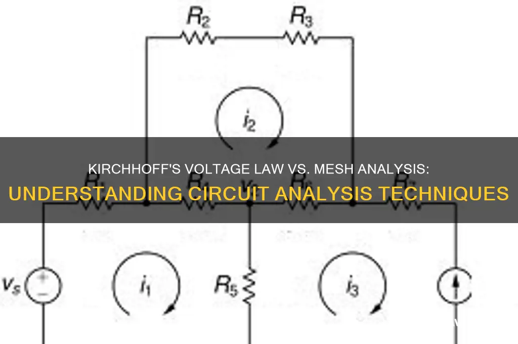
1. Identify the meshes (the "donut holes" of the circuit). 2. Assign a mesh current to each loop. All clockwise (or all counterclockwise) to keep it clean. 3. Write KVL for each mesh, accounting for the voltage drops across shared components. 4. Solve the system of equations.
Let's be real: doing this by hand for a 4-loop circuit stinks. But the process is bulletproof. It breaks down a chaotic network into a structured set of linear equations. It's the industrial method for circuit analysis.
Here's the neat part: when two meshes share a component, the current through that component is the algebraic sum of the two mesh currents. That shared voltage drop becomes part of both KVL equations. It creates coupling between the loops, which is exactly how real circuits behave. Trying to analyze each loop in isolation is like pretending the other loops don't exist. They do. KVL handles it elegantly.
Supermeshes: What Happens When You Have a Current Source Inside?
Okay, here's where textbooks lose people. What happens when a current source sits between two meshes? You can't just write a standard KVL loop through a current source because you don't know the voltage across it.
You use a supermesh.
Create a "big loop" that excludes the current source but includes the components around it. Write KVL for that big loop. Then, write a constraint equation relating the mesh currents to the current source value.
It sounds abstract until you need it. And trust me, if you are designing circuits with transistors or op-amps, you will see current sources everywhere. Mastering the supermesh technique is a rite of passage.
The general steps for supermesh analysis:
- Identify meshes that share a current source. - Remove the current source mentally and draw a larger loop encompassing both meshes. - Write KVL for that larger loop. - Write a separate equation: the difference between the two mesh currents equals the current source value.
That's it. Two equations. One current source. Problem solved.
Beyond Simple Resistors: KVL in the Real World (AC and Transients)
Phasors and Impedance: KVL in AC Steady-State
Does KVL work for AC? Absolutely. It works for everything.
The catch? You can't just add 3V and 4V and get 7V if those voltages are out of phase. In AC circuits, Kirchhoffs Voltage Law holds, but you must use phasor mathematics.
You convert resistors, capacitors, and inductors into impedances ($Z$). A capacitor has a negative imaginary impedance. An inductor has a positive imaginary impedance. You define your source as a phasor (e.g., $10 \angle 30^\circ$).
Then, you apply KVL exactly as you would in DC: the sum of the phasor voltage drops equals the phasor source voltage.
If you ignore the phase angles, your "sum" will look like it's missing voltage. It isn't. The energy is just stored in the magnetic or electric fields and returned to the circuit later. KVL is always true; your meter is just too slow to see the full picture.
Honestly, this is where Understanding Kirchhoffs Voltage Law gets really interesting for power engineers. Reactive power, power factor correction, transformer voltage regulation—all of it depends on KVL working in the phasor domain. The law hasn't changed. You just upgraded your math toolkit.
What Happens to KVL at the Exact Moment You Flip a Switch?
This is my favorite topic. Transient analysis.
The switch is open. Suddenly, it's closed. Instantaneously, the circuit topology changes. KVL must hold at every single instant in time.
For an RC circuit, the voltage isn't instantly across the resistor. It starts across the resistor and migrates to the capacitor. At $t=0+$, the capacitor looks like a short circuit. At $t=\infty$, it looks like an open circuit.
You write the KVL equation, but you include the differential equations for the reactive elements ($V_L = L \frac{di}{dt}$, $I_C = C \frac{dv}{dt}$).
Solving these differential equations using KVL is how we get the exponential charging and discharging curves. It's not magic. It's KVL, just with calculus added to the party.
Here are the key transitional states to remember when applying KVL to transient circuits:
- Inductor at t=0+: Acts as an open circuit (current cannot change instantly). - Inductor at t=∞: Acts as a short circuit (steady state DC). - Capacitor at t=0+: Acts as a short circuit (voltage cannot change instantly). - Capacitor at t=∞: Acts as an open circuit (steady state DC).
Using these, you can write KVL for the initial and final states without solving a single differential equation. Quick and dirty. Perfect for debugging.
Common Pitfalls and How to Avoid Them
- Pitfall 1: The Ground Loop Illusion. You have two different ground references in a simulation or measurement. KVL says the voltage between them is zero. It isn't. You just created a loop antenna. - Pitfall 2: Ignoring Parasitics. In high-frequency circuits, every trace is an inductor. Every via is a resistor. KVL doesn't lie. If your KVL equation doesn't match reality, model the parasitic element. - Pitfall 3: Sign Convention Switching. As I said earlier, pick a direction and stick to it. Half the errors in a bad PCB layout come from someone flipping the sign on a KVL equation halfway through. - Pitfall 4: Forgetting Mutual Inductance. In a transformer, the voltage induced in the secondary loop depends on the current in the primary. Your KVL loops are coupled magnetically. You must add a mutual inductance term ($M$) to your loop equations. - Pitfall 5: Assuming Ideal Sources. Every real voltage source has internal resistance. Every real current source has internal conductance. If your KVL simulation doesn't match the bench measurement, start adding those internal values. It's often a few milliohms that ruins a perfectly good equation.
Common Questions About Understanding Kirchhoffs Voltage Law in Complex Circuits
Does Kirchhoffs Voltage Law always hold true for any component?
Yes, with one massive caveat. It holds for lumped element models. If you are working at extremely high frequencies (RF/microwave) where the wavelength of the signal is comparable to the physical size of the circuit components, KVL breaks down as a simple summation. You need transmission line theory and field solvers. For 99% of everyday circuits (DC, Audio, low-frequency digital), KVL is absolute and inviolable.
Why do I get different results when I apply KVL to the same circuit using different loop directions?
You shouldn't. If you are getting different results, you are making a sign convention error. KVL is topologically independent. The direction of the loop just sets the sign of the terms in the equation. So long as you are consistent with the passive sign convention, the final current and voltage magnitudes will be identical. Check your polarities again.
Can I use KVL in a circuit with a dependent source?
Absolutely. In fact, dependent sources are handled exactly like independent sources in KVL mesh analysis. The only difference is that the voltage or current value of the source depends on another voltage or current elsewhere in the circuit. You write the KVL equation, substitute the dependent source relationship, and solve. It adds an extra step but changes nothing about the fundamental law.
Is KVL the same in AC and DC circuits?
Yes, the physical law is identical. The difference is purely mathematical. In DC, you are summing real numbers. In AC steady-state, you are summing complex numbers (phasors). The instant you include capacitors and inductors in an AC circuit, you must use impedance ($Z$) and account for the phase shift. If you just add RMS voltages as if they were DC, KVL will look like it's broken. It's not.
What is the difference between a loop and a mesh in KVL?
A loop is any closed path in a circuit. A mesh is a specific type of loop that does not contain any other loops inside it (it's the "window pane" of the circuit). Mesh analysis relies on using meshes because they form the minimum set of independent equations needed to solve the circuit. You can use non-mesh loops, but the equations won't be linearly independent, and you'll have a slower time solving them.
Understanding Kirchhoffs Voltage Law in Complex Circuits comes down to discipline. The math isn't hard. The physics is elegant. The only thing standing between you and a working circuit is inconsistent assumptions. Fix your polarity, trust the algebra, and let KVL do the heavy lifting.