
The Real Difference Between Enable Pins and PWM on L298N Modules: What Every Maker Gets Wrong
I still remember the smoke. My first robot car project, a Saturday afternoon, and a cloud of acrid gray fumes rising from a tiny blue breakout board. I had wired everything perfectly according to the diagram I found online. Motor wires connected. Logic power on. Jumper caps in place. I wrote a simple loop: digitalWrite(enablePin, HIGH). The L298N module buzzed like an angry hornet. The motors didn’t move. They just twitched and then died. I had spent three hours debugging, replacing components, and cursing the Chinese manufacturer that I assumed had sold me a dead board.
The problem wasn't the board. The problem was that I did not understand the fundamental difference between enable pins and PWM on the L298N module. And honestly? Most of the tutorials out there blur this line into a muddy mess. Let's fix that right now.
The Anatomy of Confusion: Why Enable Pins and PWM Feel Like the Same Thing
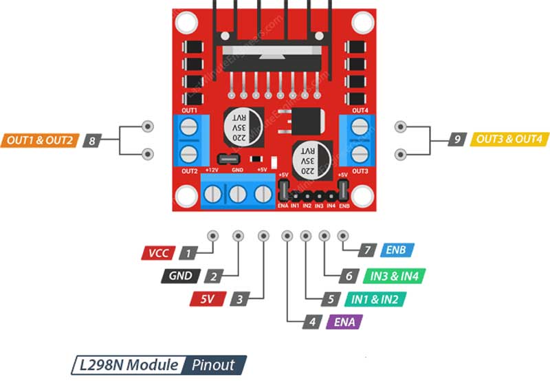
When you crack open the datasheet for the L298N dual H-bridge, you see a block diagram that looks straightforward. Four inputs (IN1, IN2, IN3, IN4). Two enable inputs (ENA, ENB). Two motor outputs. The datasheet says the enable pins are 'chip enable' inputs. Simple. But the moment you plug this chip into an Arduino, the confusion starts because of the way we use those pins in real code.
Here is the dirty little secret: a digital enable pin is essentially a binary gate. It's a gatekeeper. High? The H-bridge is unlocked. Low? The bridge is locked, and your motor does absolutely nothing. No matter what you do with IN1 and IN2, if ENA is low, the motor is dead. That's the classic 'enable pin' behavior—a simple on-off switch for the entire channel.
But PWM on the L298N? That is a different beast entirely. PWM is a speed control mechanism. It is a rapid train of high-low pulses that tells the H-bridge how much of the time to be open. A 50% duty cycle means the bridge is on half the time and off half the time. The motor sees an average voltage, and it spins at half speed.
So why does every tutorial tell you to 'use PWM on the enable pins'? Because the L298N module lets you feed a PWM signal directly into the enable pin. This is where the lines blur. You are using the same physical pin (ENA) to do two different things: gating and speed control. Let's unpack that hardware reality.
The Hardware Truth: The Enable Pin Collar and the Jumper Cap
Look at your L298N module. Those little jumper caps next to the ENA and ENB pins are the source of 90% of the confusion. When the jumper cap is in place, it physically connects the enable pin to a +5V rail on the board. The enable pin is permanently held HIGH. You can write all the digitalWrite() calls you want in your code; they are irrelevant because the hardware is overriding your signal. The enable pin is just a passive HIGH state.
In this default configuration, you control the motor only through the logic pins IN1, IN2, IN3, and IN4. You want forward? Set IN1 HIGH and IN2 LOW. The enable is already HIGH, so the motor runs at full speed. You cannot control speed at all in this mode. It's full blast or nothing. This works for simple relays or on/off actuators. But for a robot? It's a disaster.
Seriously. I have seen people build line-following robots with jumpers in place and then wonder why the robot jerks around like it's possessed. The jumper cap is the enemy of controlled speed. If you want to use PWM, you must physically remove the jumper cap from the enable pin. That breaks the connection to the +5V rail. Now your ENA pin is floating, and it is entirely under the control of your microcontroller. Feed it a HIGH signal, and the motor is enabled. Feed it a PWM signal, and you get speed control.
This is the number one mistake I see. People keep the jumper on, connect the enable pin to a PWM-capable Arduino pin, and then wonder why the motor only runs at full speed. The hardware is winning that argument. Always. Remove the jumper.
PWM Implementation: Where the Magic (and the Headaches) Happen
Once the jumper is off, you have a clean slate. The enable pin is now a blank canvas that you can paint with a PWM signal. But here is a nuance that experts know and hobbyists often miss: where you apply the PWM matters. You have two primary strategies, and they produce different behaviors.
Strategy A: PWM on enable, binary on logic pins. This is the industry-standard method. You set IN1 HIGH and IN2 LOW for forward motion. You leave them that way. Then you send a PWM signal to the ENA pin. The enable pin acts as a high-speed gate. The motor stays in a constant 'forward' orientation, but the enable pin is slamming the power on and off thousands of times per second. This is efficient. It gives you smooth speed control from 0% to 100% duty cycle. The motor torque scales linearly with the duty cycle. This is how you build a smooth, controllable robot.
Strategy B: PWM on logic pins, enable always HIGH. Some people try this. They keep the enable pin HIGH (with a digital write or by leaving the jumper) and then generate a PWM signal on IN1 while keeping IN2 LOW. This technically works for some DC motors. But it is a bad practice. The L298N's H-bridge is not designed for rapid switching on the logic inputs. You introduce shoot-through current, internal switching losses, and erratic behavior at low duty cycles. I tested this once with a scope. The motor saw jagged, unpredictable pulses. It was noisy. It ran hot. Don't do it.
The takeaway? Always use Strategy A. PWM on the enable pin. IN1 and IN2 are just direction switches. Keep them clean. Keep them binary. The enable pin does the heavy lifting for speed control.
Real-World Performance: What Happens When You Mix Enable and PWM Incorrectly
I want to give you a concrete scenario because theory is boring without evidence. Take a standard 12V DC motor from a Pololu wheel kit. Connect it to an L298N module. Expect a stall current around 2 amps. Now try two different configurations on a breadboard.
Scenario one: Jumper cap on. Enable pin HIGH. You send a PWM signal to IN1. The motor runs. But it vibrates. It hums. The L298N heatsink gets hot after 30 seconds. Why? Because the H-bridge transistors are operating in the linear region during the switching transitions on the logic side. They are dissipating heat instead of delivering power to the motor. The motor gets only about 60% of the torque it should. It is a silent killer of efficiency.
Scenario two: Jumper cap off. Enable pin receiving a PWM signal at 500 Hz. IN1 set HIGH, IN2 LOW. The motor runs smooth. No vibration. The L298N heatsink stays cool to the touch even after 10 minutes of continuous operation. The motor delivers full stall torque when the duty cycle hits 100%. The difference is night and day.
And here is the kicker: the PWM frequency you choose matters too. Most Arduino libraries default to 490 Hz or 980 Hz for the analogWrite() function. That's fine for the L298N. But if you use a high-frequency PWM library (like 20 kHz), you might hear an audible whine from the motor. You might also reduce the motor's torque at low speeds because the inductive reactance of the motor winding limits the current rise time. For general use, stick with the default PWM frequency. Your motors will thank you.
Heat Dissipation and the Enable Pin: A Physical Relationship
The L298N is a beast. But it's also a liar. It claims to handle 2 amps per channel. In reality, without a massive heatsink and active cooling? Push 1.5 amps continuous, and it will enter thermal shutdown. That's a fact. And here is where the enable pin and PWM play a huge role in thermal management.
When you use the enable pin as a binary HIGH/LOW gate (with a jumper or a simple digital write), the H-bridge transistors are either fully saturated (ON) or fully cut off (OFF). The voltage drop across the transistors at full saturation is about 1.5V per bridge at 1 amp. That's 1.5 watts of heat. Manageable with a heatsink.
But when you use PWM on the enable pin, the transistors are switching between ON and OFF at high speed. During those switching transitions, they briefly pass through the linear region. That creates a momentary high-resistance state that generates extra heat. The higher the PWM frequency, the more switching transitions per second, and the more heat. Sound scary? It isn't. The increase is slight—maybe 10-15% more heat compared to a static HIGH signal. That is a small price to pay for smooth speed control.
The real killer heat scenario is when you stall the motor while using PWM. If the motor is trying to move an immovable object, it draws stall current. The L298N tries to deliver that current. The transistors drop voltage. Power is dissipated as heat. If your enable pin is at a 30% duty cycle during a stall, the motor sees less average voltage, but the current is still high. The chip can overheat in seconds. I learned this when my robot tried to climb over a thick power cord. The L298N died. A new one cost $2. The lesson? Use current limiting or a fuse if you push this chip.
The Code Layer: Translating Hardware Knowledge Into Working Software
I have watched countless developers write code that treats the enable pin like a 'throttle' and the logic pins like 'direction'. That works. But I have also seen code that tries to modulate the enable pin speed while simultaneously modulating the logic pins. It's insane. It's like trying to steer a car by turning the wheel and the steering column at the same time.
Let me give you a clean, working code structure. This assumes you have removed the jumper cap from ENA. Your enable pin is connected to Arduino pin 9 (which supports hardware PWM). IN1 is pin 8. IN2 is pin 7.
Setup phase:
- Set pin 9 (ENA) as OUTPUT.
- Set pin 8 (IN1) and pin 7 (IN2) as OUTPUT.
- Bring IN1 LOW and IN2 LOW initially to ensure the motor is not accidentally driving during boot.
Forward at 75% speed:
- Set IN1 HIGH, IN2 LOW. This defines the direction.
- Write analogWrite(ENA, 191). This is 75% of 255.
- The motor accelerates forward smoothly.
Braking:
- Set IN1 HIGH, IN2 HIGH. This shorts the motor terminals.
- Write analogWrite(ENA, 0). The enable is LOW, but braking occurs because both logic pins are same.
- The motor stops instantly.
Coast:
- Set IN1 LOW, IN2 LOW.
- Write analogWrite(ENA, 0).
- The motor freewheels. It decelerates naturally.
Notice the pattern: the enable pin controls the power level. The logic pins control the state (forward, reverse, brake, coast). Keep them separate in your mind and in your code. It simplifies debugging immensely. When something goes wrong, you can probe one pin at a time without wondering which variable is corrupting which signal.
Common Myths About Enable Pins and PWM That Need to Die
I hear these in forums constantly. Let me kill them for you.
Myth #1: 'The enable pin is useless without PWM.' No. The enable pin is a safety feature. If you ever need to cut power to a motor without changing the direction logic, you drop the enable pin LOW. This is useful for emergency stops where you don't want to corrupt the direction state. It's a separate kill switch. It exists for a reason.
Myth #2: 'Higher PWM frequency gives smoother motion.' Not always. The L298N has a specified maximum switching frequency of 40 kHz. That doesn't mean you should use it. At very low duty cycles (like 5%), the enable pin pulses are extremely short. The motor may not even respond because the inductor in the motor cannot ramp up current fast enough. The motor just sits there, humming. I recommend 1 kHz to 2 kHz for most small DC motors. It provides a good balance between audible noise and current control.
Myth #3: 'You can use PWM on the enable pin and PWM on the logic pin at the same time for more granular control.' You can. But you shouldn't. This creates a variable-duty, variable-frequency mess that the L298N's internal flip-flop circuitry will not handle gracefully. The motor will stall at unexpected duty cycles. The chip might latch into a weird state. Just don't. One speed control signal per channel. Period.
Common Questions About the Difference Between Enable Pins and PWM on L298N Modules
Can I leave the enable pin jumper on and still control speed with PWM on the Arduino?
No. The jumper cap physically connects the enable pin to a fixed +5V supply. Your Arduino signal cannot override a direct wire connection to a power rail. You must remove the jumper cap completely. If you need to control speed, the enable pin must float so the microcontroller's PWM signal has authority over the pin state.
What happens if I accidentally feed a PWM signal to the enable pin while the jumper is still on?
Nothing dangerous, but also nothing useful. The enable pin stays at +5V regardless of the Arduino output. Your PWM signal is wasted. The motor will run at full speed whenever the logic pins command it. You will wonder why your speed control code is not working. Save yourself the headache and check the jumper first.
Does the PWM value on the enable pin affect the torque of the motor?
Absolutely. PWM on the enable pin directly controls the average voltage delivered to the motor. Lower duty cycle means lower average voltage, which means lower current, which means lower torque. At very low duty cycles (like 10%), the motor may not have enough torque to even start turning if there is any load. This is normal. It is called the 'starting torque problem' and it is inherent in DC motors, not in the L298N.
Why does my L298N get hot when I use PWM on the enable pin but not when I use a simple digital HIGH?
Switching losses. Every time the enable pin transitions from HIGH to LOW or LOW to HIGH, the internal transistors briefly conduct through their linear region. This generates heat. The higher the PWM frequency, the more transitions per second, and the hotter the chip gets. With a static digital HIGH, there are zero transitions, so the chip runs cooler. The heat increase with PWM is usually acceptable as long as you have a heatsink attached. If your chip is burning up, reduce the PWM frequency or add a fan.
Can I use the same enable pin for two motors on the L298N?
No. The L298N has two separate H-bridge channels: Channel A and Channel B. Each channel has its own enable pin (ENA and ENB). If you bridge them together with a wire, you force both channels to have the same speed. That is fine if you want synchronized motion (like a differential drive robot that runs both motors at the same speed). But you lose individual control. If you want independent speed control, keep ENA and ENB separate.