
How to Troubleshoot the Rectifier Stage in a VFD Conversion
You know that gut-wrenching moment when a Variable Frequency Drive conversion goes silent, and the only thing lighting up is the fault light? I've been there. More times than I care to count. The machine stops, production halts, and everyone looks at you like you're the one who broke it. But here's the thing—nine times out of ten, the culprit is staring you right in the face. The rectifier stage. That humble front-end section of your VFD is tougher than a two-dollar steak, but when it fails, it fails spectacularly. And during a conversion? It gets hit harder than usual.
Look—I've spent over a decade in the field ripping these drives apart, testing them, and putting them back together. I've seen brand new VFDs smoke out on day one because someone skipped the basics. So let's talk about how to troubleshoot the rectifier stage in a VFD conversion without losing your mind—or your multimeter.
The rectifier stage is the first line of defense. It takes incoming AC power and converts it to DC. Simple concept, right? But in a conversion scenario—where you're retrofitting old motor controls or swapping out a failed drive—the rectifier stage faces challenges it wasn't designed for. Voltage spikes, phasing issues, and that lovely harmonic distortion from the building's electrical system all land right here.
---
Understanding the Damage Pattern: Is It the Source or the Rectifier?
Before you crack open that drive and start poking around, you need to ask yourself a hard question. Is the rectifier stage actually dead, or is the incoming power trying to kill it? I can't tell you how many times I've seen a perfectly good rectifier get replaced, only to blow again because nobody bothered to check the supply voltage.
Honestly? This is where most technicians get it wrong. They see a blown fuse or a shorted diode, and they immediately blame the rectifier stage. But your three-phase input might be the real villain. During a VFD conversion, the existing wiring might be decades old. You could have a loose connection, a phase imbalance, or worse—someone wired it in a delta configuration when it should have been wye.
The 'Smoke Test' and What to Look For
I don't recommend literal smoke tests, but if you've got one, you'll know it. A failed rectifier stage often leaves physical clues. Cracked black plastic on the diode modules. Brown discoloration on the bus bars. That distinct smell of burnt copper and epoxy. It's a big deal when you see that, because it means the damage is catastrophic.
But sometimes the failure is silent. The VFD might power up, display a DC bus voltage, and then immediately trip on overvoltage or undervoltage. That's a dead giveaway that your rectifier stage is struggling. It might be passing voltage, but not enough current. Or it's letting AC ripple through when it shouldn't be.
Here's what I do first. I check the DC bus voltage with a digital multimeter. If you're on a 480V system, you should see roughly 650 to 680 volts DC. If you're seeing less than 600, or if the reading bounces around like a kangaroo on caffeine, your rectifier stage has a problem. Seriously—stop right there and isolate the rectifier module.
The DMM Check: Measuring the DC Bus Safely
I need to say this clearly because I don't want you getting hurt. The DC bus in a VFD holds enough energy to kill you. Even when the main power is off, those capacitors can stay charged for hours. I've seen guys get thrown across a room because they got careless. Don't be that guy.
So here's the safe procedure. Kill all power. Lock it out. Tag it out. Wait at least five minutes—ten if it's a high-capacity drive. Then use a properly rated meter to verify zero voltage on the bus. Once you're confident it's safe, you can measure the rectifier stage diodes individually.
---
The Multi-Stage Rectifier Repair: A Step-by-Step Recovery Plan
Alright, so you've confirmed the rectifier stage is bad. Now what? You can't just throw a new part at it and hope for the best. That's a rookie move, and it's expensive. I've got a systematic approach that has saved me hundreds of hours of rework over the years.
Stage 1: Discharge, Disconnect, and Document
First, you discharge those capacitors properly. Use a discharge resistor designed for the task—something rated for the voltage and power level. Don't use a screwdriver. Seriously. I've seen the aftermath of that mistake, and it's not pretty.
Next, disconnect the rectifier stage from the rest of the drive. In most modern VFDs, the rectifier is a separate module or a bolted-on assembly. You'll typically find it mounted to a heatsink near the input terminals. Take photos before you pull anything. I know it sounds basic, but when you're staring at a dozen wires and three bus bars, that photo will save your bacon.
Then document the part numbers. The rectifier stage might be a three-phase bridge rectifier module. It could be individual diodes. It might be an integrated power module that includes the braking transistor. Get the exact specifications from the manufacturer's datasheet, because generic replacements often have different forward voltage drops and current ratings.
Stage 2: The Diode Module Test and Replacement
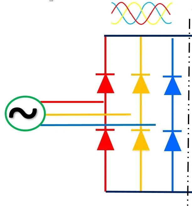
Once the rectifier stage is out, you can bench test it. Set your multimeter to diode test mode. Put the red lead on the positive output and the black lead on each of the three AC input terminals. You should see a forward voltage drop of around 0.4 to 0.9 volts. Reverse the leads and check for an open circuit—OL on the meter means the diode is blocking properly.
If any of those diodes shows a short (zero volts both directions) or an open (OL both directions), that's your failed component. Replace the entire diode module if it's a single package. Don't try to hack individual diodes out of a bridge module unless you're building a custom drive from scratch. It's just not worth the reliability risk.
---
Preventing the Next Failure: Upstream and Downstream Protection
You've replaced the rectifier stage. The VFD powers up. The motor spins. Everyone high-fives. But here's the reality check—if you don't address why it failed in the first place, you'll be doing this same repair next month.
During a VFD conversion, the most common reason for rectifier stage failure is incoming power quality issues. Look for voltage sags, spikes, and phase imbalances. I always recommend installing line reactors on the input side. They're cheap insurance. A 3% impedance line reactor can handle most of the transient energy that would otherwise punch a hole through your three-phase input rectifier.
The Soft Start Circuit: The Forgotten Gatekeeper
Here's something that catches people off guard. Many VFDs have a soft start or pre-charge circuit that limits inrush current when the DC bus capacitors first charge. If this circuit fails—maybe a relay contact sticks or a resistor burns open—the rectifier stage takes the full brunt of the inrush. That can blow diodes instantly.
Check the pre-charge resistors and the bypass contactor before you button everything up. If the soft start isn't working, your new rectifier stage won't survive the first power-up. I've learned this one the hard way, and I promise it's not fun explaining to management why you need a third rectifier module.
- Always verify the soft start circuit functions before replacing the rectifier. - Measure the resistance of the pre-charge resistors against the schematic. - Listen for the bypass contactor clicking in after a few seconds. - If there's no click, the control board might be the real problem.
---
A Note on IGBTs and the 'Shoot-Through' Problem
Now, this is where things get technical. The rectifier stage and the inverter stage (those IGBTs) talk to each other through the DC bus. If an IGBT fails short—which happens often in a catastrophic drive failure—it can dump high voltage back through the DC bus into the rectifier. You might replace the rectifier, power up, and watch it fry again because the IGBTs are still bad.
I tell my students this all the time: when troubleshooting a VFD conversion, never test the rectifier stage in isolation. Always check the IGBT module for shorts between the collector and emitter. A quick resistance check with your multimeter is better than nothing, but ideally you want to use an IGBT tester or an isolation meter.
If you find a shorted IGBT, you need to replace both the inverter module and the rectifier stage. Don't skimp. The surviving components might have taken damage you can't see. It's a big deal to do a partial repair on a drive that has seen a major fault, because the remaining stress on the diodes and IGBTs will shorten their lifespan drastically.
The DC Bus Capacitors: Silent Partners in Crime
Look—I said I'd keep it conversational, so here it is. The DC bus capacitors can kill your rectifier stage even when they look fine. Old, dried-out electrolytics have higher equivalent series resistance (ESR). This creates ripple current that the rectifier wasn't designed to handle. The rectifier has to work harder to keep the bus voltage stable, and it eventually overheats.
During a VFD conversion, if the drive is more than five to seven years old, I strongly recommend replacing the DC bus capacitors as a preventive measure. It's not strictly necessary for the rectifier stage to function, but it will dramatically improve the reliability of the entire drive. Honestly, it's one of those things that separates a good repair from a great one.
1. Check the capacitance values against the nameplate specifications. 2. Look for bulging vents or leaked electrolyte at the base of the cans. 3. Measure the ESR using an ESR meter if you have one. 4. If any capacitor is out by more than 20%, replace the entire bank.
---
Common Questions About Troubleshooting the Rectifier Stage in a VFD Conversion
How do I know if my rectifier stage is actually bad versus a control board issue?
If you have no DC bus voltage at all, but you have proper input voltage, the rectifier stage is almost certainly dead. If you have DC bus voltage but the drive won't run or faults immediately, it could still be the rectifier, but it might also be the control board. I always measure the DC bus voltage first. If it's stable and within range, I move to the control board. If it's unstable or low, I focus on the diode module and the DC bus capacitors.
Can I replace just the individual diodes in a bridge module instead of the whole module?
You can, but I don't recommend it unless you have no other choice. The three-phase input bridge is manufactured as a matched set inside the module. Replacing individual diodes with generic parts changes the thermal characteristics and the forward voltage balance. This creates hot spots that lead to premature failure. Replace the whole rectifier stage module.
What's the most common cause of rectifier failure during a VFD conversion?
In my experience, it's voltage transients from the line side. When you're converting an older system, the existing wiring often doesn't have proper surge suppression. Lightning strikes, switching transients from nearby equipment, or even a large motor starting on the same feeder can send a spike through the rectifier stage that blows the diodes. Always install surge suppressors and line reactors.
Is it safe to power up a VFD with a suspected bad rectifier to test it?
Absolutely not. If the rectifier stage is shorted, you could cause a phase-to-phase fault that destroys more components and creates an arc flash hazard. Test the rectifier with the power off using a multimeter. If you need to power it up to check control functionality, disable the three-phase input by using a low-voltage DC supply on the bus instead.
How long should a rectifier stage last in a properly installed VFD conversion?
A well-designed rectifier stage running within its rated limits should last the life of the drive—easily 15 to 20 years in a clean environment. But during a conversion, you're inheriting someone else's electrical problems. If you take the time to fix the upstream issues and replace aging capacitors, you can expect that lifespan. If you just swap the module and power it back up, you might get six months.
Troubleshooting the rectifier stage in a VFD conversion isn't rocket science. It's methodical detective work with a multimeter and a healthy respect for high voltage. Take it step by step, check your assumptions, and never skip the safety precautions. Your drive, your motor, and your body will thank you for it.