
How to use a voltage divider for AC signals: The Real Deal
You’ve got an AC signal—maybe it’s a sine wave from a function generator, maybe it’s the output of a sensor. It’s too hot for your microcontroller’s ADC, and your first instinct is to grab two resistors and build the classic voltage divider. Good instinct. But if you wire that up without thinking about frequency, you’re in for a rude surprise. Seriously. I’ve seen engineers spend an entire afternoon debugging a “broken” ADC because their voltage divider for AC signals was acting like a low-pass filter.
Let’s fix that. I’m going to walk you through the practical side of this—the math, the gotchas, and the real-world fixes that a decade of oscilloscope time has taught me.
Why a DC Voltage Divider Fails (and What You Need Instead)
The classic two-resistor divider works beautifully for DC. You pick your ratio, you drop the voltage, you move on with your life. AC is a different animal because it involves frequency, and frequency introduces a new player: capacitive reactance. Your signal doesn’t just “see” resistance anymore; it sees impedance.
Impedance is the Secret Sauce
For a DC signal, impedance and resistance are the same thing. For an AC signal, you have to consider the impedance of every component, including your own probes and the stray capacitance on your breadboard. Look—if you try to use a voltage divider for AC signals without accounting for this, the ratio you calculate at 60 Hz will look completely different at 10 kHz. It’s a big deal.
Here’s the core idea: the total impedance of a component in an AC circuit is a combination of resistance (R) and reactance (X). For a capacitor, reactance is inversely proportional to frequency. So at low frequencies, a cap looks like a high impedance. At high frequencies, it looks like a short. That’s the trap people fall into.
The Math is Still Simple (With a Twist)
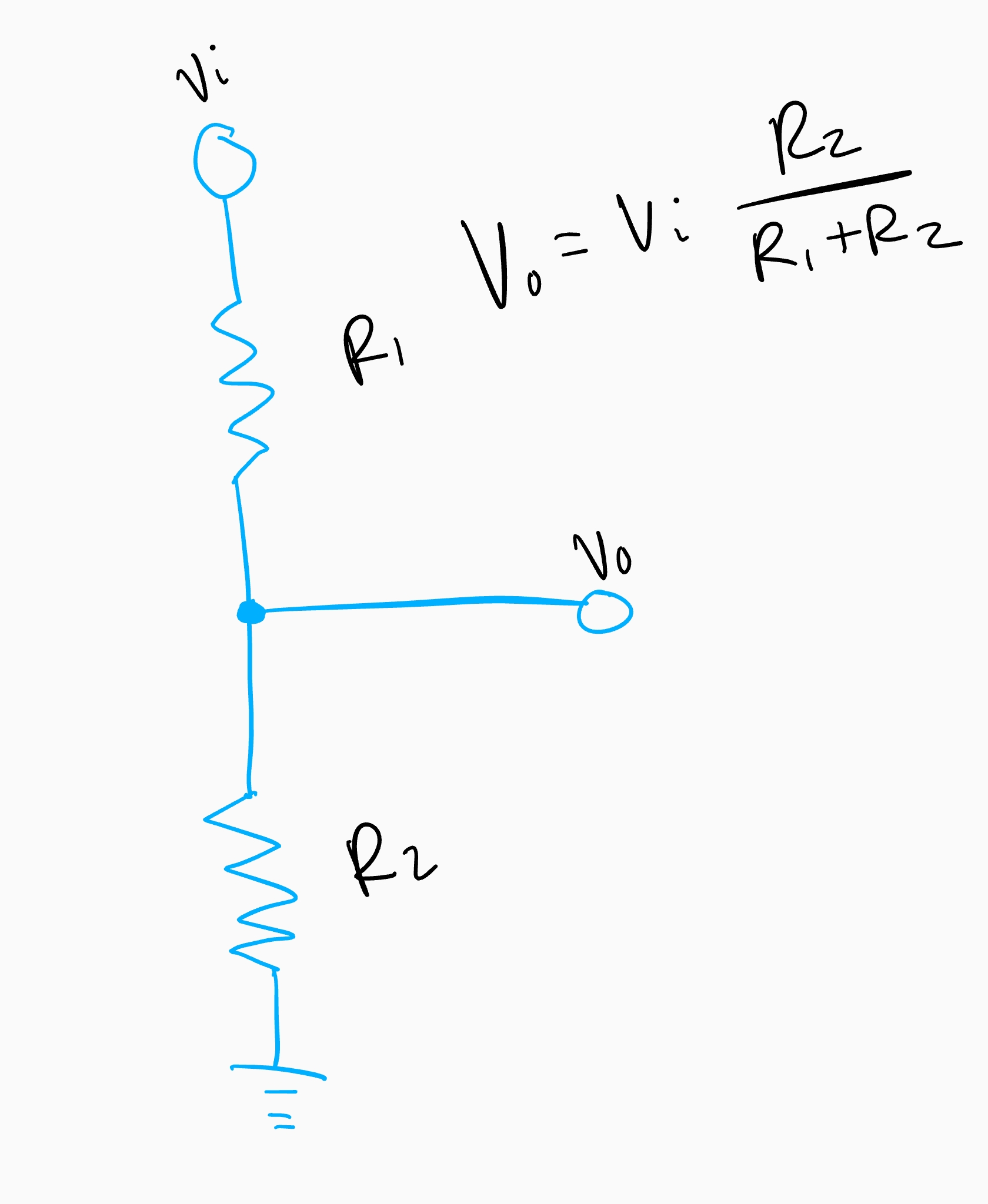
You still use the voltage divider formula, but instead of R1 and R2, you substitute Z1 and Z2—the total impedance of each leg. For a pure resistive divider, Z is just R. For a capacitor, Z = 1/(2 π f * C). The twist? Impedances can have a phase angle. The output voltage’s magnitude might be right, but the phase could be shifted. For many applications (like audio or simple measurement), you care mostly about the amplitude. For others (like zero-crossing detection), the phase shift will kill you.
So, the rule of thumb: if you want a frequency-independent voltage divider for AC signals, keep it purely resistive and ensure the divider’s total resistance is much lower than any parallel capacitance. Honestly? That’s easier said than done above 100 kHz.
Practical Circuit Design: The “Loaded” Divider
Let’s say you’re building a simple probe to measure a 10V peak-to-peak AC signal with a 3.3V ADC. You pick a 10:1 ratio. Good start. But then you connect it, and the reading is off by 20%. What happened?
The Loading Effect (and Your ADC’s Dirty Little Secret)
Your ADC has an input capacitance. Typically, it’s around 10 to 50 pF. That cap is effectively in parallel with your bottom resistor (R2) in the divider. At DC, you never see it. But at 1 MHz, that 10 pF cap has a reactance of about 16 kOhms. If your R2 is 10 kOhms, you’ve just changed the bottom leg impedance significantly. Your neat 10:1 ratio just became a 4:1 ratio across frequency. It’s a big deal.
To fight this, you have two options:
- Make R2 very small—like 100 ohms. Then the 16 kOhm reactance of the parasitic cap is irrelevant. The downside? Your divider draws a lot of current from your signal source.
- Add a buffer—an op-amp configured as a voltage follower. This isolates the divider from the capacitive load of the ADC. This is the cleanest solution for precision work.
Parasitic Capacitance is the Real Enemy
Your circuit board itself is a capacitor. Traces next to each other, a ground plane underneath a signal trace—these all add small amounts of capacitance. For a high-impedance voltage divider for AC signals, these parasitics dominate the behavior above a few hundred kHz.
I once spent an hour trying to figure out why a 1:1 scope probe was showing a 100 MHz sine wave with a 50% attenuation. The culprit? A tiny blob of solder that increased the capacitance of the probe tip to ground by about 2 pF. At that frequency, 2 pF is a 800 ohm short. You have to think about the physical layout.
Here’s a quick list of things that will ruin your day:
- Long jumper wires—they act as inductors and antennas.
- Breadboards—the internal capacitance between rows is ~5 pF per intersection.
- Probe ground leads that are too long—the inductance makes the divider ring.
- Unshielded signal paths near a switching power supply.
Step-by-Step: Designing Your First AC Divider
Let’s walk through a real scenario. You have a 5V RMS audio signal (roughly 14V peak-to-peak). You want to drop it to 1V RMS to feed a line input. You want the response to be flat from 20 Hz to 20 kHz.
- Choose your series resistor (R1). Keep it between 1 kOhm and 10 kOhm. Lower gives better bandwidth but loads the source. I usually start at 4.7 kOhm.
- Calculate R2 for the ratio. You need a 5:1 divider. With R1 at 4.7 kOhm, R2 should be about 1.18 kOhm. Use 1.2 kOhm (standard value).
- Account for the load. Your next stage has an input impedance of 10 kOhm with a 20 pF cap. The 10 kOhm load is in parallel with R2, effectively making the bottom leg ~1.07 kOhm. The ratio shifts slightly. You can adjust R1 up a bit to compensate.
- Check the frequency response. Calculate the -3 dB point of the RC filter formed by R2 (1.2 kOhm) and the load capacitance (20 pF). RC time constant is 24 ns, which gives a cutoff of about 6.6 MHz. You’re safe for audio.
- Test it. Always scope the output before connecting it to your expensive equipment. Look for roll-off at the upper end of your frequency range.
If you follow those steps, your voltage divider for AC signals will behave predictably. You’ll have a clean, flat response across your bandwidth.
The Frequency Limit: When Resistors Aren’t Enough
There comes a point where even a low-value resistive divider stops being purely resistive. This happens when the skin effect in the resistor body starts to matter, or when the lead inductance creates a resonance. Above 50 MHz, you’re better off using a transmission-line transformer or a capacitive divider.
Capacitive Dividers for High-Frequency Work
For RF signals (say, 100 MHz and above), you switch to a voltage divider for AC signals made entirely of capacitors. The ratio is set by the capacitance values: Vout/Vin = C1/(C1+C2). The beauty of this approach is that you don’t dissipate any power (ideal capacitors don’t heat up). But the downside is that the divider only works for AC—it blocks DC completely. This is exactly how 10x oscilloscope probes work. They use a 9 pF series capacitor and a 1 pF parallel capacitor, with a trimmer to compensate for the scope’s input capacitance.
Compensation is Key
If you ever hook up a 10x scope probe and see a square wave turn into a rounded mess, you’re seeing a poorly compensated capacitive divider. The fix is adjusting the trimmer capacitor inside the probe until the square wave corners are crisp. This same principle applies to any custom voltage divider for AC signals you build for high frequencies. You need a variable capacitor in parallel with one of the divider legs to tune out the parasitic effects.
Common Questions About How to Use a Voltage Divider for AC Signals
Can I use a potentiometer for an AC voltage divider?
You can, but be careful. Potentiometers have wiper capacitance and inductance that change with position. For low-frequency AC (under 1 kHz), a pot works fine as an adjustable divider. For higher frequencies, the wiper contact can become a source of noise and non-linearity. I recommend a fixed resistor network instead.
What happens if I use a divider with the wrong frequency?
The output amplitude will be lower than expected, and you’ll see a phase shift. For a purely resistive divider, this only happens when the load capacitance dominates. For a capacitive divider, the ratio is fixed across frequency (assuming no resistive paths). The wrong frequency in a capacitive divider just means the impedance is different, but the ratio stays the same—perfect for RF.
Why does my divider work at 50 Hz but not at 10 kHz?
You’re hitting the corner frequency of a parasitic RC filter. Either the source has high output impedance, or the load has input capacitance. At 10 kHz, a 100 pF load in parallel with a 10 kOhm resistor creates a -3 dB point at about 160 kHz. That shouldn’t be a problem. If you’re seeing drop at 10 kHz, your parasitic capacitance is much larger—maybe 1 nF or more. Check your layout.
Do I need to match the resistors for impedance?
Not in the same way you match for transmission lines. For a simple voltage divider for AC signals, you care more about the ratio and the loading effect. Impedance matching is only necessary when the signal travels over a long cable (more than 1/10th of the wavelength) and you want to avoid reflections. For audio and low-frequency work, ignore matching.
What’s the best way to test my AC divider?
Use a function generator to sweep the frequency from your lowest to highest expected value. Use an oscilloscope to measure the output amplitude. Plot the gain versus frequency. If it’s flat within a few percent, you’re golden. If you see a roll-off, you need to either reduce the resistor values or add a buffer. Don’t trust a multimeter for AC above a few hundred Hz—they average the signal and give you an RMS value that hides distortions.