
Rth Junction-to-Case vs Ambient Explained
You've just spent a weekend building a custom power supply, and everything looks perfect. Then, you fire it up, and that voltage regulator gets hot enough to fry an egg. You check the datasheet, and there it is: Rth. But which Rth? The datasheet throws two numbers at you—Rth Junction-to-Case and Junction-to-Ambient—and they couldn't be more different. Honestly? Picking the wrong one is like driving with a map of Paris while you're in Tokyo. It's a big deal.
Look—thermal resistance is the language your components use to tell you how miserable they are. Every semiconductor, from a tiny MOSFET to a massive IGBT, has a soul. Its soul is the junction. And that junction hates being hot. Rth (thermal resistance) is the barrier between that hot junction and the outside world. But here's the kicker: that barrier is not a single number. It's a path with multiple checkpoints. Understanding the difference between Rth Junction-to-Case and Rth Junction-to-Ambient is the difference between a design that works for years and one that fails in weeks.
What Exactly is Rth? The Thermal Resistance Analogy
Think of electricity. You have voltage, current, and resistance. Now think of heat. You have temperature difference (voltage), heat flow in watts (current), and thermal resistance (resistance). It's that simple. Rth is measured in degrees Celsius per watt (°C/W). It tells you how many degrees the temperature will rise for every watt of power you dump into the device.
But here is where the analogy gets a little messy. In an electrical circuit, you usually have a single path to ground. In a thermal system, the heat has multiple escape routes. The Junction-to-Case path is the direct highway from the silicon die through the package to the outer surface of the component. The Junction-to-Ambient path is the scenic route—through the package, out into the air, and then slowly dissipating into the room. Seriously, they are not the same road.
I once had a client who designed a motor controller using a TO-220 package. He calculated his heat sink based on the Rth Junction-to-Ambient value from the datasheet. He thought, "25 °C/W, that's fine." The device lasted about 15 minutes. Why? Because the Junction-to-Ambient value assumes the device is sitting naked in still air. He had a heat sink. He needed the Junction-to-Case value. That mistake cost him a prototype board and a lot of pride.
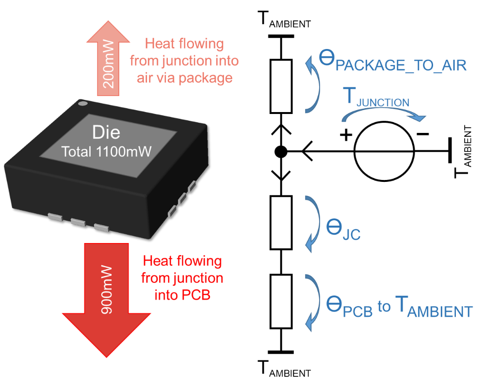
Breaking Down the Thermal Path: The Junction-to-Case Measurement
What is the Junction-to-Case (RthJC) Parameter?
Rth Junction-to-Case (often labeled RthJC or RθJC) is the thermal resistance from the actual silicon junction to the outer surface of the component case. This is the "internal" resistance of the package itself. It's a measurement of how well the heat moves from the chip, through the die attach material, through the lead frame or substrate, and finally to the top or bottom of the package. This number is typically very low. For a decent TO-220, you might see 1.5 °C/W to 3 °C/W. For a power module, it could be under 0.5 °C/W.
This value is critical because it is the bottleneck you cannot avoid. No matter how good your heat sink is, you cannot lower the Rth Junction-to-Case. It is baked into the component design. The manufacturer measures this in a controlled lab setting, usually with the case bolted to a cold plate or an infinite heat sink. It's a best-case scenario for the internal path. Does it reflect reality? Only if you use a perfect heat sink with zero thermal resistance. Spoiler: you don't.
Why You Should Care About Mounting and Thermal Interface Material
Here is where the hands-on experience kicks in. The datasheet gives you a perfect Rth Junction-to-Case value. But that value assumes the case is at a uniform temperature. In reality, you slap a thermal pad or some grease between the component and the heat sink. That introduces a new thermal resistance—the Rth case-to-sink. And the mounting pressure? Miss it, and you might as well be using a cotton ball as a thermal interface. Seriously.
I always tell engineers: "The datasheet lies." Not maliciously, but it lies. The Rth Junction-to-Case is a number you can trust, but only if you understand the test conditions. Use it as the starting point. Then add your own Rth case-to-sink (typically 0.1 to 0.5 °C/W for good grease, or 1.0 to 2.0 °C/W for a cheap pad). Then add the Rth sink-to-ambient for your heat sink. The total from junction to ambient is the sum of all these resistances. The Junction-to-Case is just the first leg of the relay race.
The Junction-to-Ambient Measurement: The Whole Picture
What is the Junction-to-Ambient (RthJA) Parameter?
Rth Junction-to-Ambient (RthJA or RθJA) is the thermal resistance from the silicon junction all the way to the surrounding air. This includes the internal package resistance, the external surface resistance, and the convection and radiation to the environment. This number is always much higher than the Junction-to-Case value. For a small SOT-23 package, you might see 200 °C/W to 300 °C/W. For a TO-220 with no heat sink, you might see 60 °C/W to 80 °C/W.
This is the number you use when you are not using a heat sink. It assumes the component is soldered to a standard PCB (usually a specific size, like 1 square inch of copper) and sitting in still air with no forced airflow. The manufacturers love to give you this number because it makes the component look usable. But here is the trap: the Rth Junction-to-Ambient value is heavily dependent on board layout, copper thickness, ambient temperature, and airflow. Change one variable, and the number becomes meaningless.
The Fiendish Trick of the Datasheet
Look—every major semiconductor company has a standard way to measure Rth Junction-to-Ambient. It's called the JEDEC standard. The standard specifies a test board with a certain number of copper layers and trace widths. But your board is not that board. Your board is cramped, has vias everywhere, and probably has a ground plane that is too small. The RthJA from the datasheet is a reference, not a design guarantee. If you use it as a guarantee, you are playing with fire.
I once worked on a LED driver design. The datasheet for the driver IC said RthJA was 45 °C/W. That sounded great. We let the IC run at 2 watts of dissipation. That's a 90 °C rise over ambient. At 25 °C ambient, the junction would be at 115 °C. Within spec, right? Wrong. The board we used had a tiny copper pour for heat spreading. The actual RthJA was closer to 70 °C/W. The junction hit 165 °C. The IC shut down. The lesson? Rth Junction-to-Ambient is a suggestion. Rth Junction-to-Case is a fact. Always measure or simulate the real thermal path.
Practical Application: Which Value Do You Use?
When to Use Junction-to-Case for Heat Sink Design
If you are designing a heat sink solution, you use Rth Junction-to-Case. Period. This is the non-negotiable rule. Here is the calculation:
1. Determine the power dissipation (P) of the device. 2. Find the maximum allowed junction temperature (Tj_max) from the datasheet. 3. Choose your maximum ambient temperature (Ta_max), say 50 °C. 4. Calculate the maximum allowed total thermal resistance: Rth_total = (Tj_max - Ta_max) / P. 5. Subtract the Rth Junction-to-Case from the total. 6. Subtract the Rth case-to-sink (thermal interface material). 7. The remaining value is the maximum allowed Rth sink-to-ambient for your heat sink.
This is the correct way. It gives you a budget for the heat sink. It accounts for the fact that the heat sink is the most controllable part of the system. The Junction-to-Case is fixed. The heat sink is your variable. You can always add more fins, more airflow, or a bigger block of aluminum. You cannot change the internal package resistance.
When to Use Junction-to-Ambient for No-Heat-Sink Designs
You use Rth Junction-to-Ambient only when the device is not bolted to a heat sink. This applies to small signal transistors, low-power regulators, and many SMD components. But even then, you must be careful. The RthJA value is a function of the PCB copper area. Many manufacturers now provide multiple RthJA values for different board configurations. For example:
- RthJA with 1 square inch of copper on a 2-layer board: 62 °C/W. - RthJA with minimal copper: 95 °C/W. - RthJA with 2 ounces of copper on a 4-layer board: 45 °C/W.
Choose the one that matches your design. If you are unsure, add a safety margin of 20% to 30%. Thermal runaway is not a fun debugging session. It is a fire hazard.
Common Questions About Rth Junction-to-Case vs Ambient
Can I use the Junction-to-Ambient value if I have a small heat sink?
No. If you attach any heat sink, even a small clip-on fin, the thermal path changes completely. The Rth Junction-to-Ambient value becomes irrelevant. You must use the Rth Junction-to-Case value and then model the heat sink and interface resistance separately. The heat sink creates a new, lower resistance path to the ambient air. The original datasheet value assumes no heat sink.
Why does the datasheet show both values if Junction-to-Case is more accurate?
The Rth Junction-to-Ambient value is useful for initial feasibility checks and for low-power components that don't need a heat sink. It gives you a quick estimate of whether the device will survive in a typical PCB layout. However, for any design where power dissipation is significant (say, over 0.5 watts), you should always use the Junction-to-Case value and design a proper thermal management system. The datasheet provides both because they serve different purposes.
What is a typical thermal resistance for thermal grease?
A good quality thermal grease, when applied correctly in a thin layer, has a thermal resistance of about 0.1 to 0.3 °C/W for a standard TO-220 package. Thermal pads are higher, usually 0.5 to 1.5 °C/W. The exact value depends on the thickness of the layer and the contact pressure. Too much grease is actually worse than a thin, even layer. The goal is to fill the microscopic air gaps, not to create a big blob of silicone paste.
Does the ambient temperature affect the Junction-to-Case value?
No. The Rth Junction-to-Case value is a material property of the package. It does not change with ambient temperature. However, the junction temperature does depend on the ambient temperature. The Rth tells you the temperature rise per watt. The actual junction temperature is the ambient temperature plus that rise. A high ambient temperature eats into your thermal budget, so you need a lower Rth sink-to-ambient to compensate.
How do I measure the actual thermal resistance in my circuit?
You can measure the case temperature with a thermocouple or an infrared thermometer. Then, calculate the junction temperature using the thermal resistance formula. Alternatively, many power devices have a temperature-sensitive electrical parameter (TSEP), like the forward voltage of a diode or the base-emitter voltage of a transistor. You can calibrate this parameter and measure the junction temperature indirectly. This is the most accurate method for verifying your thermal design and is a standard practice in the industry.