
Understanding Star Connection Winding Configurations
I still remember the smell of ozone and burnt copper from my first year as a winding technician. A brand-new 500 HP motor was smoking on the test bench because someone ignored the basics of star connection winding configurations. They thought a Y-configuration was just a way to save copper. They were wrong. Seriously, that mistake cost the shop three weeks of rebuild time and a client who never came back. So, let me save you from that exact headache. Whether you're a plant engineer, a motor rewinder, or just a curious nerd who loves three-phase power, understanding how these windings actually work is the difference between a motor that hums and one that hums then dies.
The Core Concept: Why Star (Y) Isn't Just a Shape
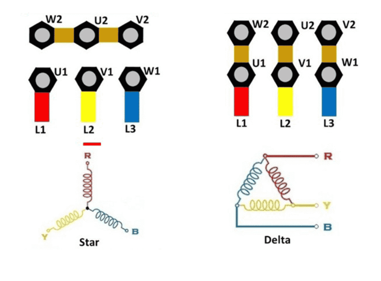
When we talk about a star connection winding, we're describing how three individual phase windings share a common point. That common point is the neutral. It's a big deal. Look—every winding has a start and an end. In a star configuration, all three ends (or all three starts, depending on your design) tie together at one node. The other three terminals become your line connections. That's it. But that simple geometry changes everything about how the motor behaves.
The beauty of this arrangement is voltage reduction across each winding. In a delta connection, each winding sees the full line-to-line voltage. In a star connection winding, each phase winding sees only the line-to-neutral voltage. That's roughly 58% of the line voltage. Honestly? This is why we use star configurations for high-voltage motors. If you've got a 4160 V system, you don't want 4160 V across a single coil unless it's built like a tank. Star gives you a safety margin and cuts insulation stress in half compared to delta.
But here's where most textbooks gloss over the practical part: the neutral point isn't always grounded. I've seen installers assume it must be bonded to earth. Not necessarily. In an ungrounded star system, that neutral floats. It's a critical detail for harmonic control and fault detection. I'll say it again: understanding star connection winding configurations means knowing when to ground that neutral and when to let it dance alone.
Let's not forget the current side. In a star winding, the line current equals the phase current. No division, no multiplication. That makes calculations straightforward. But the torque curve? That changes. Star winding motors typically have lower starting torque than their delta counterparts. That's the trade-off. Lower voltage across each winding means lower current inrush, but it also means the motor might not accelerate a heavy load without help.
Star vs. Delta: The Practical Showdown
I've been in winding shops where old-timers argue about this like it's a religious debate. It's not. It's physics with a pinch of application. A star connection winding is the gentle giant. It starts soft, draws less surge current, and runs cooler at light loads. Delta is the brute. It hits hard, pulls massive inrush, and delivers full torque from the first rotation.
Most industrial motors above 100 HP are designed for star-delta starting. You start in star to limit the current spike, then switch to delta after the rotor spins up. I've commissioned dozens of those starters. The timing relay has to be perfect. Too short a transition and the motor is still accelerating when you slam it into delta—giant current spike, potential trip. Too long and you waste heat in the star mode windings.
Here's a reality check: not every motor can tolerate star-delta switching. If the winding is designed exclusively for delta, trying to start it in star will leave you with a motor that runs at roughly one-third of rated torque. Seriously. I had a customer who tried to run a 200 HP delta-wound compressor motor in star because they misread the nameplate. It sat there, humming, getting hot, and moving no air. We had to rewind it as a dual-voltage star configuration. Cost them double.
The Voltage & Current Dance in Star Windings
Let me walk you through the numbers, but I'll keep it human. Imagine a 480 V three-phase system. In a star connection winding, the voltage across each phase coil (phase voltage) is 480 V divided by the square root of three. That's about 277 V per coil. This is why 277 V lighting circuits exist—they tap one phase and neutral from a star-wound transformer. So the same math that powers your motor also powers the lights in a commercial building. It's all connected.
Current behavior is simpler. Line current equals phase current. No tricks. But the relationship between line voltage and phase voltage has a huge impact on winding design. For a given horsepower, a star-connected motor uses more turns of thinner wire compared to delta. More turns increase the back EMF, which limits the current. Thinner wire means more resistance losses, but the reduced voltage across each coil means the insulation system can be cheaper. It's a balancing act that every winding engineer lives with.
Now, let's talk about neutral current in three-phase balanced systems. In an ideal world, the neutral carries zero current. The three phases cancel each other out at the star point. But I've never seen a perfectly balanced motor in the field. Not once. Harmonic currents from VFDs, slight winding imbalances from manufacturing, or even a bad connection upstream will cause neutral current to flow. That's why I always spec a neutral bus bar rated for at least half the line current in VFD applications.
One more thing about voltage: if you're rewinding a motor for a different voltage, don't just change the wire gauge. You have to recalculate the turns per coil. I've seen shops try to convert a 460 V delta to a 460 V star by just reconnecting the leads. Doesn't work. The magnetic flux saturates the core, and you get a motor that overheats and dies in hours. Understanding star connection winding configurations means respecting the turns ratio.
Common Winding Patterns and Their Characteristics
There are a few basic patterns you'll see in the field. The most common is the single-layer concentric winding. Each pole group has coils of different spans, nested inside each other like Russian dolls. These are easier to wind by hand and are typical for smaller motors. But the star connection at the neutral point can get messy if you don't have a proper phase separator.
Then there's the double-layer lap winding. This is the workhorse of large industrial motors. All coils have the same span, which gives better magnetic balance and lower harmonic content. In a star connection winding with lap coils, the neutral point is usually a heavy buss ring or a bolted connection inside the stator housing. I've seen some star connection winding configurations that use a dedicated neutral ring made of copper bar stock, while others just twist the six leads together. The twist method works for small motors, but for anything above 50 HP, use a proper ring. Otherwise, you get hot spots and eventual failure.
Muscle memory helps here. When you're splicing the neutral joint, use a crimp connector rated for the full motor current. Not just for the phase current. I learned that lesson when a neutral joint glowed red after a short circuit test. The phase conductors were fine, but the star point became the weak link. That's a failure mode that trips up even experienced winders.
Testing and Troubleshooting Star Wound Motors
Before you even power up a rewound stator, you need to verify the star point. Use a multimeter set to continuity. Check between each phase lead and the neutral point. All three should show the same low resistance. If one is open, you've got a broken connection inside the winding. If one is shorted to ground, you have insulation failure. I always do this test twice. Once before varnish dip, once after. The varnish dip can shift wires and break a solder joint.
Insulation resistance testing (megger) is non-negotiable. For a star connection winding, you test between each phase and ground, and also between phases. But here's a trick: test from the neutral point to ground as well. If the neutral insulation is compromised, you'll get a path to ground through the star point even when all phase insulations are fine. I caught a motor that way once. The neutral ring was touching the stator core because a tie-off string had come loose during winding.
Surge testing is another level. It compares the winding pattern between phases. In a healthy star winding, the surge waveform from phase A to B should match B to C and C to A. Any deviation indicates a turn-to-turn short or a wrong connection. I've found reversed coil groups inside star windings that appeared fine on resistance test but showed up immediately on surge. Trust the surge tester. It sees what Ohm's law misses.
- Verify neutral continuity using a low-resistance ohmmeter. A 0.5 ohm difference between phases is a warning sign.
- Check tightness of neutral bolts. Loose connections arc and carbonize the insulation over time.
- Megger at 500V minimum for low-voltage windings, 2500V for medium voltage. Record the polarization index.
- Perform surge comparison on all three phases. Look for pattern separation that exceeds 10%.
Common Mistakes in Field Connections
The biggest one is wiring a star motor to a delta starter. I see this all the time when a facility replaces a motor without checking the nameplate. The motor runs, but it draws high current and runs hot. The motor protection trips randomly. Everyone blames the motor, but it's the connection. If you have six leads, and your starter is wired for delta, but the motor is star, you can damage both in minutes.
Another classic error: marking the leads incorrectly. A star connection winding has a specific lead numbering system (T1, T2, T3 for line; T4, T5, T6 for neutral end). If you swap T4 and T1, you get a short circuit at the terminal box. I've seen terminal boxes explode from this. Seriously. The arc flash is real. Always ring out your leads from the winding to the terminal before connecting power.
Grounding the neutral point unnecessarily is a subtle mistake. In a wye-delta starting system, the neutral is often left ungrounded during start. If you permanently ground it, you create a single point of failure. A ground fault anywhere in the winding becomes a direct short through the neutral. I recommend an ungrounded star neutral for motors that run on VFDs or have high harmonic content. The floating neutral allows the motor to tolerate some imbalance without tripping.
Practical Design Considerations for Star Windings
When you're specifying a star connection winding configuration, think about the load first. High-inertia loads like fans and flywheels need that soft start. Star winding gives you lower starting torque, which means less mechanical stress on the coupling and the load. But if you're driving a reciprocating compressor or a rock crusher, star starting might not provide enough torque to break the initial friction.
For dual-voltage motors, star connection is essential. A common design is 460/230 V. In the low-voltage configuration (230 V), the motor is connected in delta. In the high-voltage configuration (460 V), it switches to star. That's because the winding is actually designed for the lower voltage delta connection. The star connection for high voltage keeps the volts per turn constant. I've wired hundreds of these. The terminal block has to be clearly labeled, or someone will try to run it in low-voltage star mode and burn it up.
Thermal management is different in star windings. Because each coil sees lower voltage, the current density is typically higher. More copper loss per volume of slot. If the ventilation in the motor is poor, a star winding can run hotter than its delta counterpart at the same horsepower. I've added external cooling fans to star-wound motors in dust collector applications. The ambient temperature plus the higher current density creates a thermal death spiral if you don't plan for it.
- Slot fill factor: Star windings need more turns, so slot fill is critical. Overstuff the slot and you damage insulation during insertion.
- Wire size: Thinner wire for star means higher resistance. Use temperature-class H or better insulation to handle the heat.
- Phase to neutral insulation: It's often lower voltage rating than phase to phase, but don't skimp. The neutral point can see surge voltages.
- Bracing: More turns means more end-turn mass. Use adequate lacing tape to prevent vibration and fretting.
When Star Isn't the Answer
Honestly? There are situations where star connections cause more problems than they solve. If you have a constant-speed, constant-load motor like a pump that runs 24/7 at full load, delta is often better because it gives slightly higher efficiency (fewer turns, lower resistance loss). Star winding adds that extra 2-3% resistance loss from the thinner wire. Over a year of continuous operation, that's real money in electricity.
Also, if you're trying to retrofit an old motor that was designed for delta, don't force a star connection. The magnetic circuit is already optimized. Changing the connection pattern changes the flux density. You'll get high no-load current, overheating, and possible core damage. I've seen people try to convert delta motors to star for soft starting. It's a hack that works sometimes, but it's not reliable. Use a VFD instead. Star connection winding configurations are a design choice made during winding, not a field modification.
For motors with integral pole-changing windings (like Dahlander connections), star configurations are tricky. The star point has to be switched along with the pole count. I've seen control schematics that look like spaghetti because the contractors have to reconfigure the neutral. If you're not comfortable with the switching logic, bring in a specialist. A miswired Dahlander in star mode can short half the winding and drop the rotor into the stator.
Common Questions About Understanding Star Connection Winding Configurations
What is the main advantage of a star connection winding over a delta connection?
The main advantage is voltage reduction across each coil. In a star connection winding, each phase winding sees only line-to-neutral voltage, which is about 58% of line voltage. This allows for lower insulation requirements and reduces stress on the winding. It also provides a neutral point for grounding and protection schemes. For high-voltage motors, this is often a necessity rather than a choice.
Can a star winding connection be used with a VFD?
Absolutely. In fact, many VFD-driven motors use a star connection winding to manage the high-frequency voltage spikes from the drive. The lower phase voltage helps reduce the stress on the insulation system. However, you must pay attention to the neutral point. A floating star neutral is usually preferred with VFDs to avoid circulating harmonic currents through ground paths. Some drives even monitor the star point for ground fault detection.
How do I identify a star winding on a motor nameplate?
Look for a symbol that looks like a Y or the word 'star.' The nameplate will list the connection voltage. For example, a motor rated at 460 V star will show 'Y 460 V' or 'Star 460 V.' If you have six leads coming out of the motor, the connection diagram is usually printed on the plate. If the motor is dual-voltage, one of the connections will be star. When in doubt, ring out the leads with a multimeter. In a star winding, you will find three groups of two coils that all share a common connection.
What happens if a star winding motor is connected to a delta power supply?
If you connect a motor that is wound for star connection winding to a delta supply (three-phase without neutral), the motor will see a higher voltage across each coil. For example, a motor designed for 277 V per coil in star will see 480 V per coil in delta. This causes excessive current draw, overheating, and almost certain failure of the winding insulation within minutes. The motor will run about 73% faster if it's a synchronous design, but induction motors will just saturate and overheat.
Is the neutral point of a star winding always grounded?
No, not always. In many industrial applications, the neutral is left ungrounded or grounded through a high impedance resistor. An ungrounded star neutral allows the motor to continue running with a single phase-to-ground fault. This is common in systems that require high reliability. A solidly grounded neutral is typical in low-voltage distribution systems but is less common for motor windings in medium-voltage applications. I always recommend checking the system grounding philosophy before connecting the neutral.